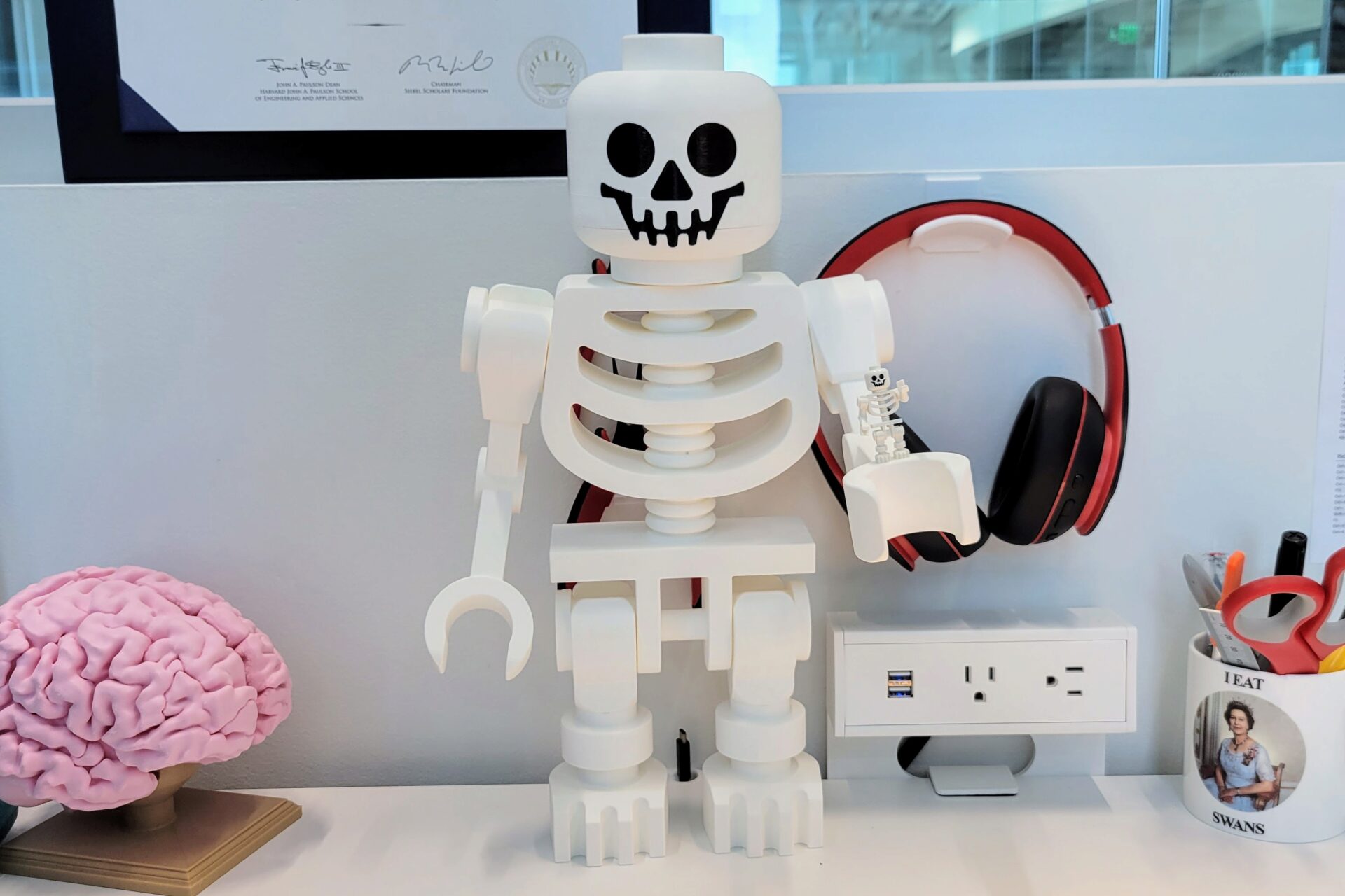
Mega Lego Skeleton
Posted: 2021 October 4
Last updated: 2021 October 12
TL;DR
It’s a big skeleton. Happy Halloween!
The moral of the story for this project is: Even if you start with a model of what you’re trying to create, it can be non-trivial to make it into a 3D printable project. This holds for any manufacturing method: you always have to figure out how to produce and assemble it (with the right tolerances!) for your particular fabrication method.
All the models are available on Prusa Printers and Thingiverse.
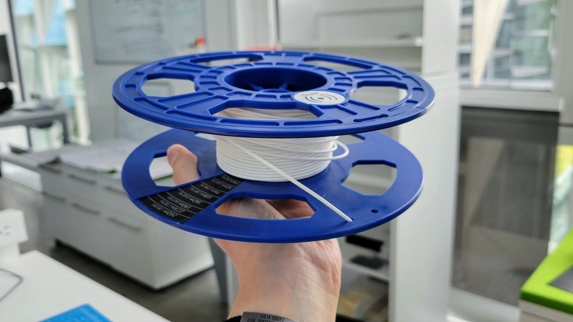
This starts with a roll of filament that a friend found in a dumpster: a still-sealed 750g spool of white Dremel PLA. So I had to find something ridiculous to make use of this gift bestowed upon me by the garbage gods. The answer came from a Facebook group where someone posted a 5x scale Lego skeleton. It’s almost Halloween month – perfect!
But then I looked at the model on Thingiverse. The cylinders have 16 sides. In its defense, the creator made it to be printed at a 1:1 scale to match regular Lego minifigures, but I knew that it would look bad scaled up. But hey, someone made a version that’s smooth for larger prints! The result was enormous (up to 80 MB) .obj files that just rounded everything out and lost all of the definition of the sharp edges. Plus, there were still two other significant issues. First, Lego parts are designed for injection molding, not 3D printing; that means no flat surfaces to place on the print bed, and (in the existing models) a lot of curves and suspended sections requiring lots of supports, and almost certainly a bad-looking print finish. Second, tolerances. It was hard to tell what the tolerances were for the joints and attaching the head, and they didn’t seem to be created for a specific model scale.
I came to the same conclusion I had many times before when looking for models on Thingiverse: I should just redo this myself from scratch.
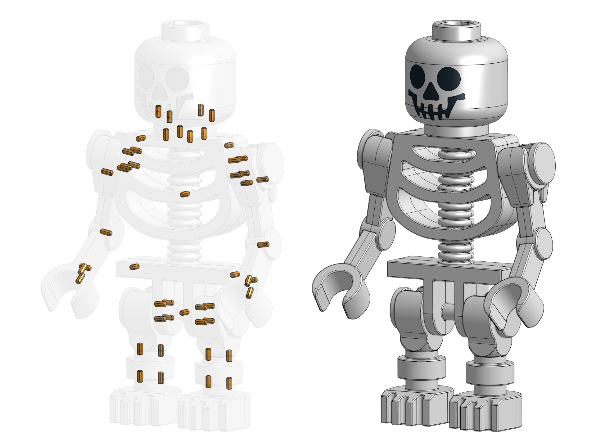
I kind of dreaded the prospect of trying to precisely measure all of the tiny parts of a Lego skeleton. Luckily, the internet came to the rescue in the form of GradCAD. I found a pair of models from a user called Yauhen: a classic Lego skeleton minifigure (left below) and fantasy era skeleton minifigure (right below). They represent slightly different generations of Lego skeletons.
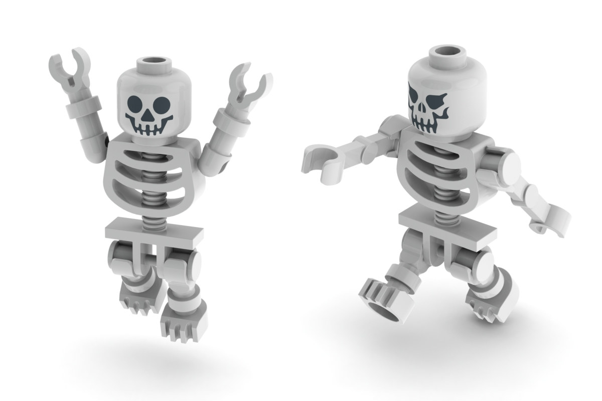
The creator included the SLDPART files, so even though I wasn’t using Solidworks for my modeling, I could import the objects into OnShape and preserve exact geometry to make my modifications. I ended up using a combination of these models. For the most part, they’re the same. They just differ in the arms/shoulders and the faces. I opted to use the hinge shoulder joint of the newer model, rather than the ball and socket joint (with some modifications – more on that later) and the classic skeleton face of the older model because it’s more classic and less creepy.
Just to make this more interesting, I decided to scale this model up to a ridiculous size: ten times the original Lego size, meaning 1000x the volume.
Arms
Tolerances
I started with the arms because I wanted to start with a sanity check: Could I design tolerances that would let me snap the arm onto and off the shoulder joint without breaking, and that would allow the arm to be positioned without slipping. This is asking a lot of printing tolerances, but there are some things I can do to help myself out here. The biggest thing here is print orientation. Especially with PLA, the print is weakest along the layer lines. By printing the clip part of the upper arm flat, I snapping on the arm wouldn’t put stress along the layer lines. To make things consistently easier here, I made a decision that I would always adjust tolerances by adjusting the outer part – i.e., the clip part of the arm and the holes for studs to fit into.
A quick note here: I chose this version of the arm because it means one less joint type to figure out tolerances for. I also figured that I could make a smoother, stronger, easier to attach joint with a cylinder, rather than a sphere. The tradeoff is fewer degrees of freedom, but this is a giant decorative toy, not a robot.
I made the smart choice to print test parts for tolerances before going all in. I started with too large of a radial tolerance on the clip (0.2 mm) and too small of a horizontal tolerance on the clip opening (leaving the default 28 mm from the original model). By the end, I ended up with a clip opening of 30 mm, and 0 mm for the radial tolerance. Having no radial tolerance actually makes sense here: For the clip to stay tight on the peg, it needs to clamp down on it. Because the clip is open, it is slightly pulling open the opening to achieve this while still fitting on the peg. PLA is prone to creep, so this might loosen up over time, but again: it’s a toy. If I need to, I can add some tape to the inside of the clip in the future to tighten it up.
With the tolerances sorted, it was time for some creative liberties. This “real” Lego skeleton arm is straight. To be honest, it looks a little ridiculously long. There is a different Lego part with a bent arm (I remember this from my childhood being used for battle droids.) But that has the hand horizontal, which isn’t great for holding most Lego accessories. So I combined them: bent elbow with a vertical hand. Sorry, Lego purists.
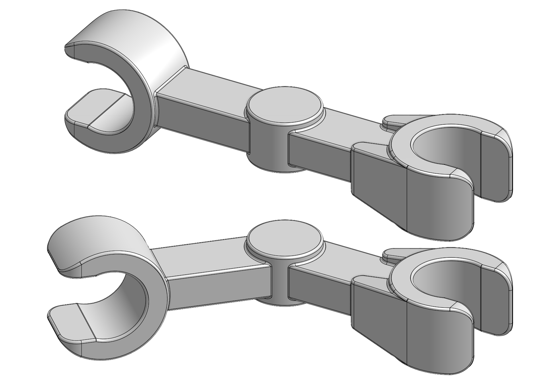
Break it up
Back to a practical problem: How on earth do I print this? I know that I need to print the clips horizontal, so I have to split it up to do that for both clips (hand and shoulder). But even if I separate the hand (the clip on the left in the above picture), the remainder of the arm still doesn’t have a nice flat surface on one side for printing. The most feasible option seems to be splitting the whole arm in half down the middle. Then I can connect super glue the halves together, and super glue the hand onto the end. (Super glue and PLA are great friends.) To test this idea out, I printed just the shoulder clip section of the two arm halves and super glued them together. I wanted to see how easy it was to align the pieces, and whether I could get close enough that the shoulder clip joint would still work as expected.
It turns out that alignment is hard. As soon as I squished the halves together, the liquid super glue cured very quickly – not a lot of time for realignment. I was able to line it up well enough for the clip to work as expected, but I was worried about how this would scale to the whole arm and, eventually, probably the whole torso. I needed a way to keep the parts aligned during assembly.
Luckily, this is a problem that engineers have already solved: dowel pins! I can print holes into the insides of both arm halves, then use 3D printed dowel pins to line them up as I assemble it.
Typically, dowel pins are cylinders. That’s really easy to make when they’re turned on a lathe, but that’s not great for 3D printing. We want to print the pins flat on the bed; if they’re printed upright, the stress will be along the weak layer lines and they’ll snap easily. But cylinders don’t print well horizontally, because you have very steep overhangs. I could use pins with a square profile instead, but it turned out to be tricky to fit the holes into some of the smaller parts because of the large cross section with sharp corners. So I compromised between a square and circle: octagons! This only requires printing a 45 deg overhang, and allows for a large cross section that will fit in tight curved areas (like the legs, later on).
To make it easier to insert the dowel pins, I added a chamfer to the ends of the pins and to the openings of all the holes. It’s all on the inside of the parts, so none of it will be visible, but makes assembly a lot easier.
However, none of this will help with alignment if I can’t get the tolerances just right. (Are you sensing a theme?) If the pins are too loose in the holes, they won’t actually keep anything lined up. Too tight, and you can’t get it together in the first place. More test prints! I ended up with a 0.1 mm tolerance on each side. That means my 4.0 mm pins required 4.2 mm holes. To my surprise, this worked well for holes printed vertically and horizontally. I expected that I would need a larger tolerance for horizontal holes, due to bridging on the tops of the holes, but there’s such a short bridging distance on top of an octagon that it’s basically negligible.
Legs
After the arms, the legs are easy! I still have to print them in parts to avoid overhangs, but I’ve now worked out the system of dowel pins for alignment and the tolerances for the joints.
So we go from the whole leg:
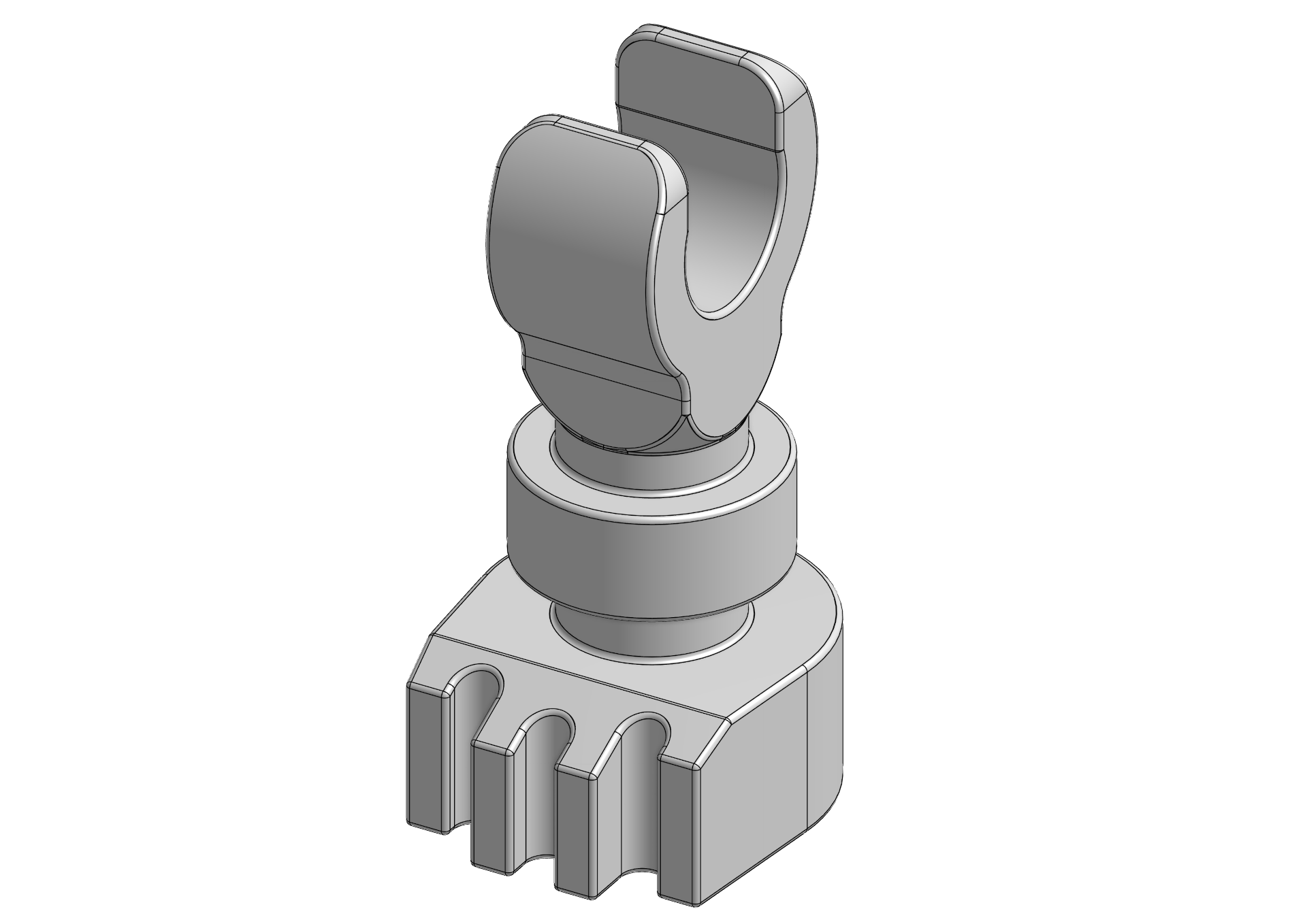
To three parts:
Here you can see the holes for the pins, and in particular how close to the edges they are. Here’s where the square pins would have caused problems in my design, unless I made the pins a lot smaller.
Luckily, Lego skeletons don’t have different right and left feet, so I can just print the same thing twice.
Body
I was nervous about the body for two reasons. First, it’s really big. It takes 7-8 hours to print each half, depending on the settings. So if something goes wrong partway through (foreshadowing), it’s potentially a lot of time and filament wasted. Second, I had to employ the same technique as I did with the arms: splitting the whole thing in half and printing it in two pieces, which then have to be glued back together with as little seam as possible.
To create a smooth peg for clipping on the arms and legs, I’d already decided to print those separately, vertically (that way there’s no stair-stepping on the tops of the semi-cylinders, and no seams in the middle for the clips to catch on).
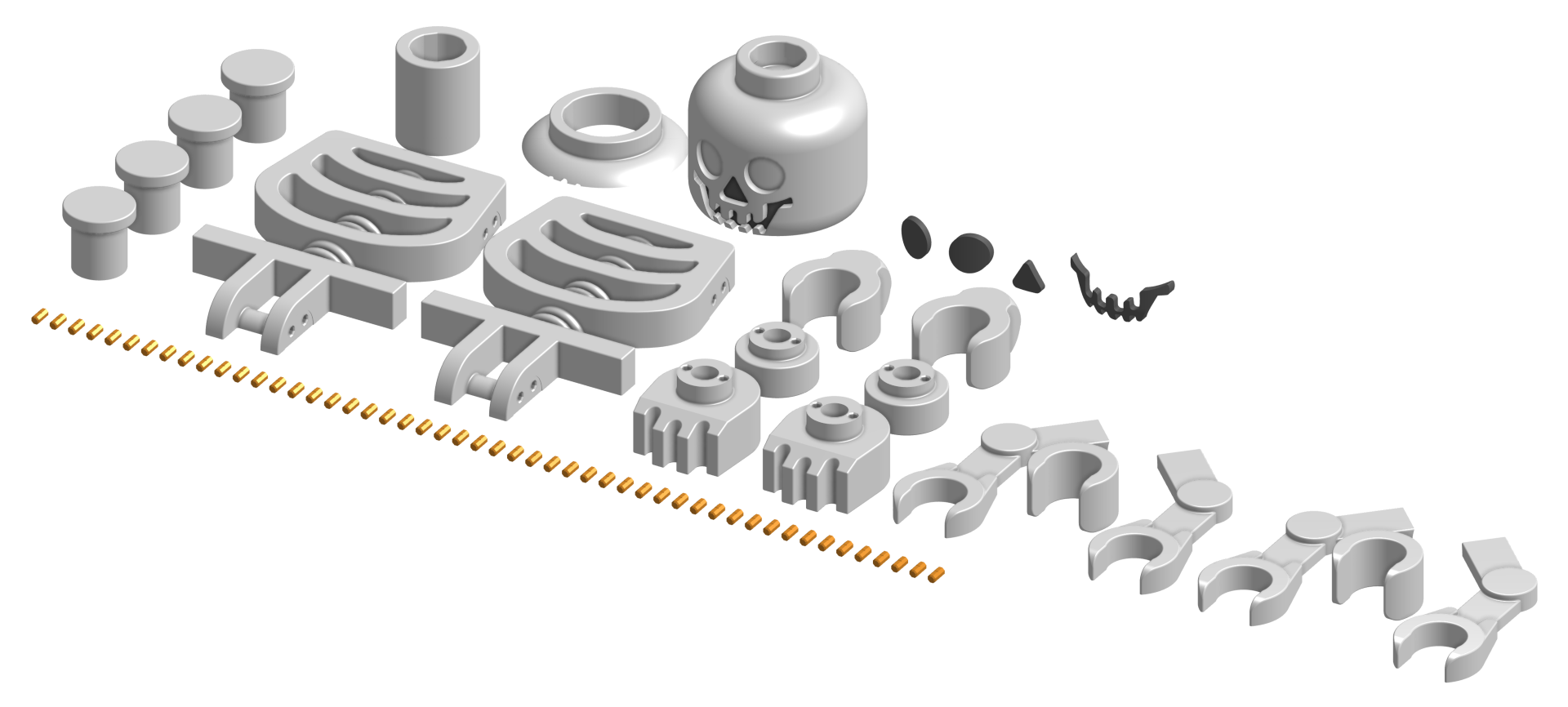
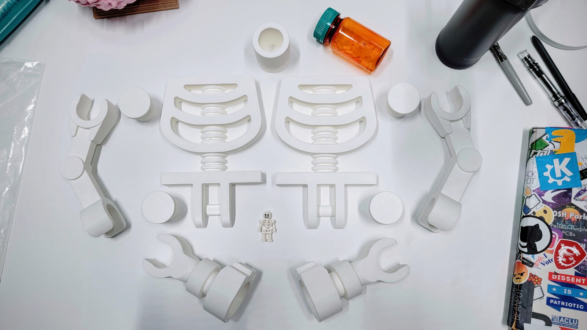
Let’s look at what this should all look like, once it’s put together.
That’s a lot of pins. 50 pins, to be exact.
Printing
This is everything that I need to print. 25 parts, plus the 50 pins. I’m pretty sure this is the highest part count of anything I’ve 3D printed.
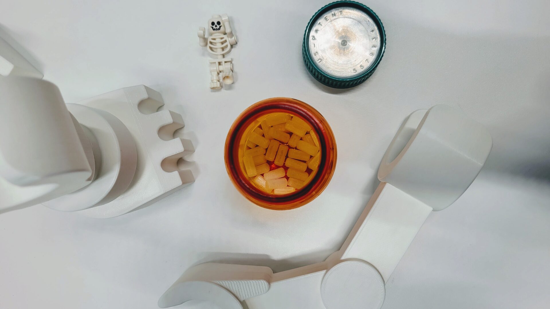
The pins were easiest. So I printed them first. Then it turned out the easiest way to store these pill-sized pins is… in a pill container. Please don’t swallow them.
I started small with my skeleton prints. After all, I was using unfamiliar dumpster filament. First, the leg parts, then one of the arms, then the other. Then that second arm failed. The print jammed partway through. I did some googling: Dremel suggests printing at 220 C, compared to my typical 205 C. That might explain it. So I try printing a pair of shoulder pegs, successfully. Emboldened, I jump into printing half of the torso and wake up to half a print and a clogged nozzle.
What’s going on? Is it my printer, or the mystery filament? I’m a scientist, so I decide to experiment and try taking the filament to print on my lab’s printer – also a Prusa i3 MK3S. It perfectly printed half an arm and both halves of the torso. Guess it’s time to take apart my extruder and dig into that issue. (Later update: It seems like the issue may have been caused by a loose teflon tube in my hotend.)
On a final round, I throw in all the remaining parts I need to print: the neck, arm half, two more pegs, and hand, then head home for the night. When I come in the next morning, the prints did finish, but with a tiny layer shift a few millimeters from the start of the print. Ordinarily, this wouldn’t be a huge issue. Sure, it’s a slight aesthetic defect if you look closely. But I have pins with very tight press fit tolerances. And now they don’t fit in the holes. I pulled out my tiny files and file down the insides of a few of the holes on the arm half. I’m able to get in two of the pins, which surprisingly still line up the halves correctly. That’s good enough. I don’t actually need all four pins here.
You might notice that I haven’t mentioned designing or printing the head yet. Because I haven’t done that yet. There are a couple of challenges I’m still considering how to tackle, so I’ll come back to that later. After all, a headless skeleton for Halloween still seems pretty fitting.
Partial Assembly
With everything but the skull made, I’m confident enough to start gluing things together. I started with the legs, because they seemed the most forgiving: there are no flat flush seams that I need to get perfectly aligned and squished together.
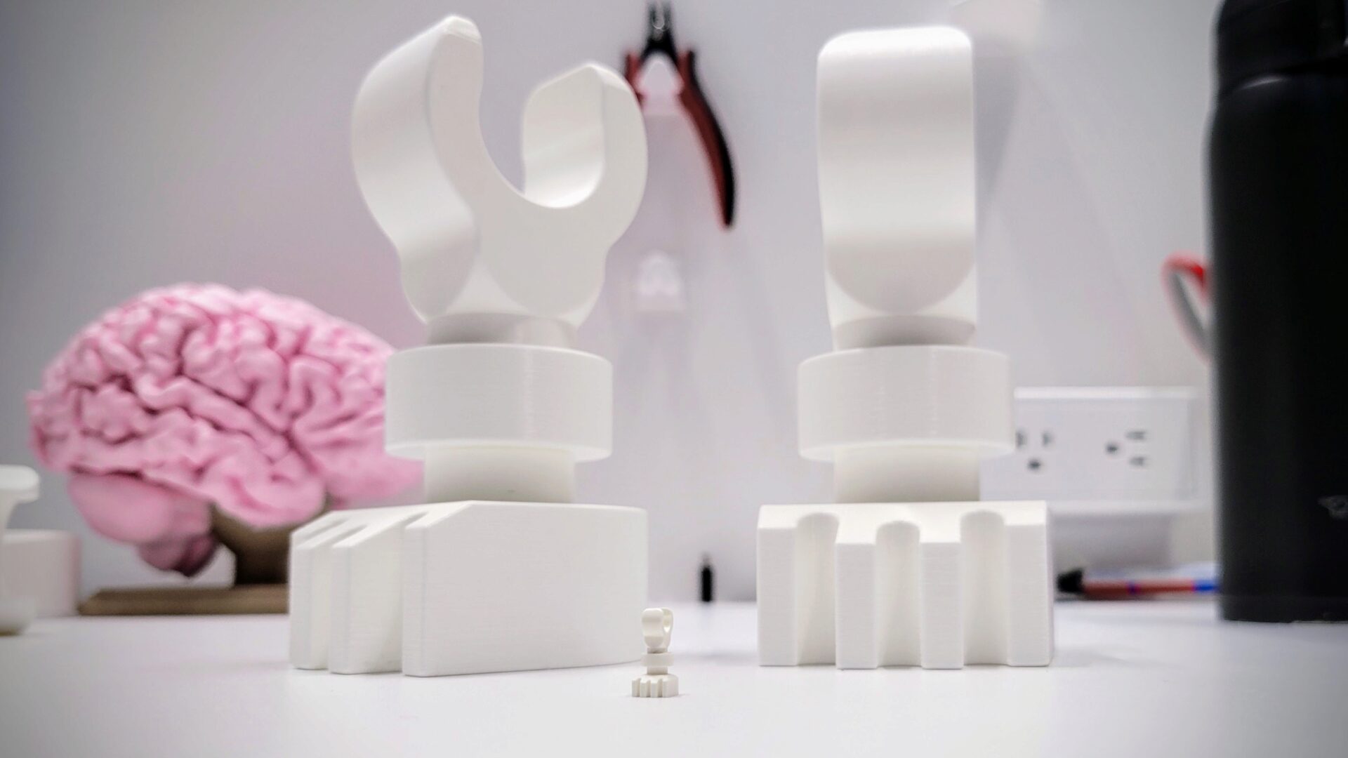
Lego skeleton leg for scale. You can start to tell how ridiculously big this thing is going to be.
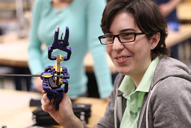
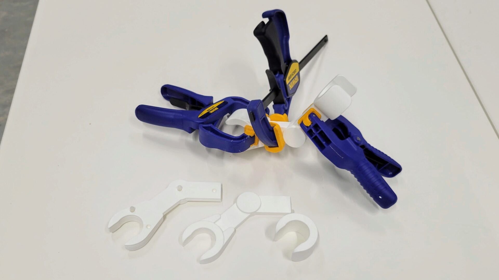
The arms proved a little bit trickier. I was now using gel super glue, because that’s what I had on hand in the lab. It doesn’t seem to cure nearly as fast. And the arm halves didn’t want to stay fully squished together. Perhaps there was a little bit of warping off of the printbed that I hadn’t noticed earlier, or the printer frame isn’t quite square, so the parts are all ever so slightly off from perfect, then pull each other that way when assembled. Whatever the cause, it’s nothing that I can fix with a ton of clamps. (It’s not the first time.)
Head
The last piece is the head. I’ve got to make a mega version of this:

I waited to make the head for a couple of reasons. First, it’s big, and I wanted to make sure I had my process down before I failed and wasted a lot of filament. Plus, I didn’t want to accidentally use up all of the filament here, then have to make half an arm out of a slightly different shade of white.
I also wasn’t sure how to tackle the curves of the head. It has curves on both the top and bottom, so if I print it monolithically, it’ll look pretty crappy on the bottom. But I also really don’t want to have a seam in the middle of the head. Now that I’ve successfully printed and glued together the rest of the flat seams on the skeleton, I’m less scared of the seam, so I’m open to printing it in two pieces. If you look at the picture of the real Lego head, you can see that the seam from the injection molding is near the top of the head, where the cylindrical portion ends. I instead decided to put the seam on the bottom curve of the head, to make it less obvious at a glance.
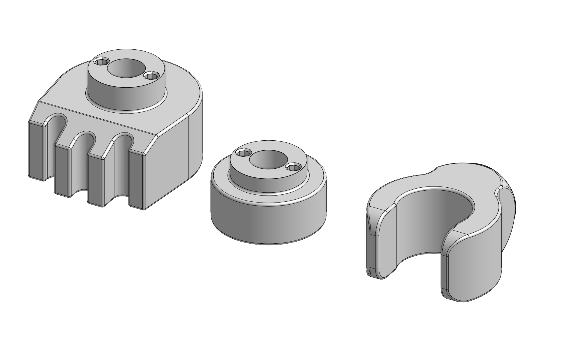
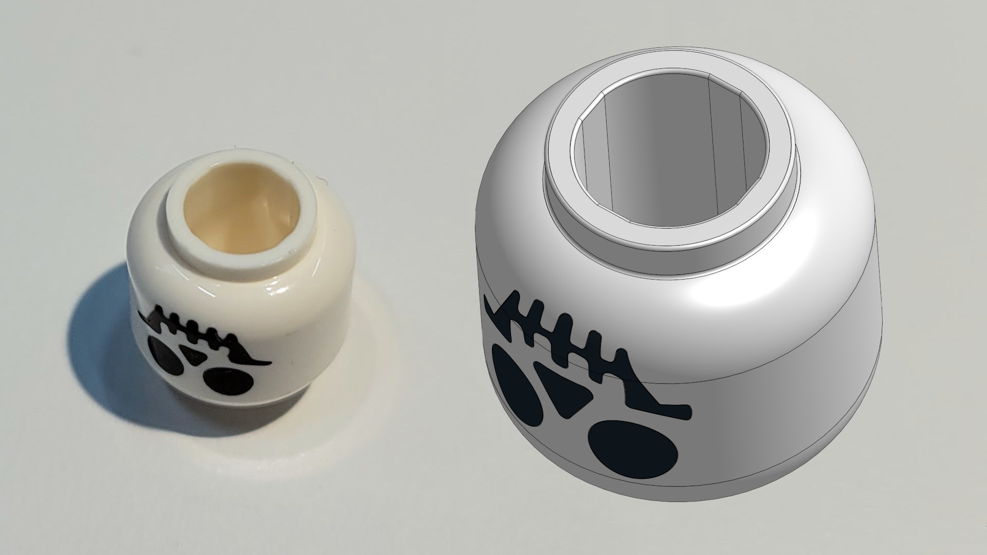
Neck tolerances
There’s also another new tolerance I have to figure out for the head: the opening where it connects to the neck. Lego employs a clever technique here, which is also replicated in my starting model. Instead of making a perfectly cylindrical hole, there is a slightly oversized cylindrical hole with flat sections set into it that make contact with the neck peg. This serves a couple of purposes (this is used throughout Lego’s parts, including the underside of regular bricks). Since the top of the head is closed, this gives space for air to go in and out, preventing a vacuum or high pressure that makes is hard to get the head on and off. I also think this gives some play in the tolerances; they only need to worry about the contact at four points, rather than the whole cylinder. This reduces friction, and when you apply force to attach or remove a part, it’s distributed over a smaller area, increasing the pressure you’re applying to move the piece. It’s really clever. Here’s what it looks like on the actual Lego skull, and in the CAD model. It’s pretty subtle.
Back to the actual tolerances: I again printed a couple of test parts. The diameter of the cylinder is less important than the distance between the flats, as long as it’s enough larger than the 48 mm neck peg. I actually found that the best fit was when the flats were 47.9 mm apart – a negative tolerance. I didn’t print the full height of the neck (that’s a lot of filament), so this may end up having too much friction when putting on the whole head. In that case, I’ve always got my trusty files.
The face
This just leaves the challenge of the face. One option is to use the MMU2S I have on my printer. I’m skeptical of this. Even before my printer started jamming with the dumpster Dremel filament, it had trouble loading and unloading that filament more than others. It seems to have a certain stretchiness to it that I’m used to seeing with silk filaments (though to a lesser extent than those). As with silk filaments, this means you need a higher print temperature and worse zitting on the z-seam. Plus, I want to make this publically available on Thingiverse and Prusa Printers, and very few people have an MMU. Making a non-MMU version makes it more accessible.
Instead of the MMU, I could just leave hollow spots in the face, more like an actual skull. But that doesn’t match with my aesthetic of over-engineered replication of the One True Lego. There’s also a non-printed alternative: paint the face onto a blank head after the fact. That’s no fun because I don’t get to print it. I also worry that it would be hard to make look good (even with a nice vinyl-cut stencil), especially with the risk of paint being sucked into the layer lines and spreading horizontally.
That leaves the assembled option: Print the skull with hollows, print the face parts separately, and then (you guessed it!) super glue it all together. Unfortunately, this means I have to use support material for the hollows. It also means printing the face parts is going to be tricky. I could print them with flat backs, so the outer/visible face parts are the top surface. But this would mean you get that stair-stepping effect due to the shallow slope. To avoid this, I’ll have to print them upright, which means support material to hold up all the features. I’m less worried about bad-looking supported surfaces here, though, since those won’t be visible once the skull is assembled. I might need to pull out my set of trusty tiny files to get it together, but that’s a sacrifice I can make.
Print it
The skull parts came out great. In PrusaSlicer, I switched from the “speed” option to the “quality” option, in hopes that I wouldn’t encounter any more weird artifacts or layer shifts. (Since the layer shifts on the other parts, I did re-tension my belts and re-tighten my motor grub screws.) Miraculously, I even managed to have just enough filament to finish printing the skull. This is what down to the wire looks like.
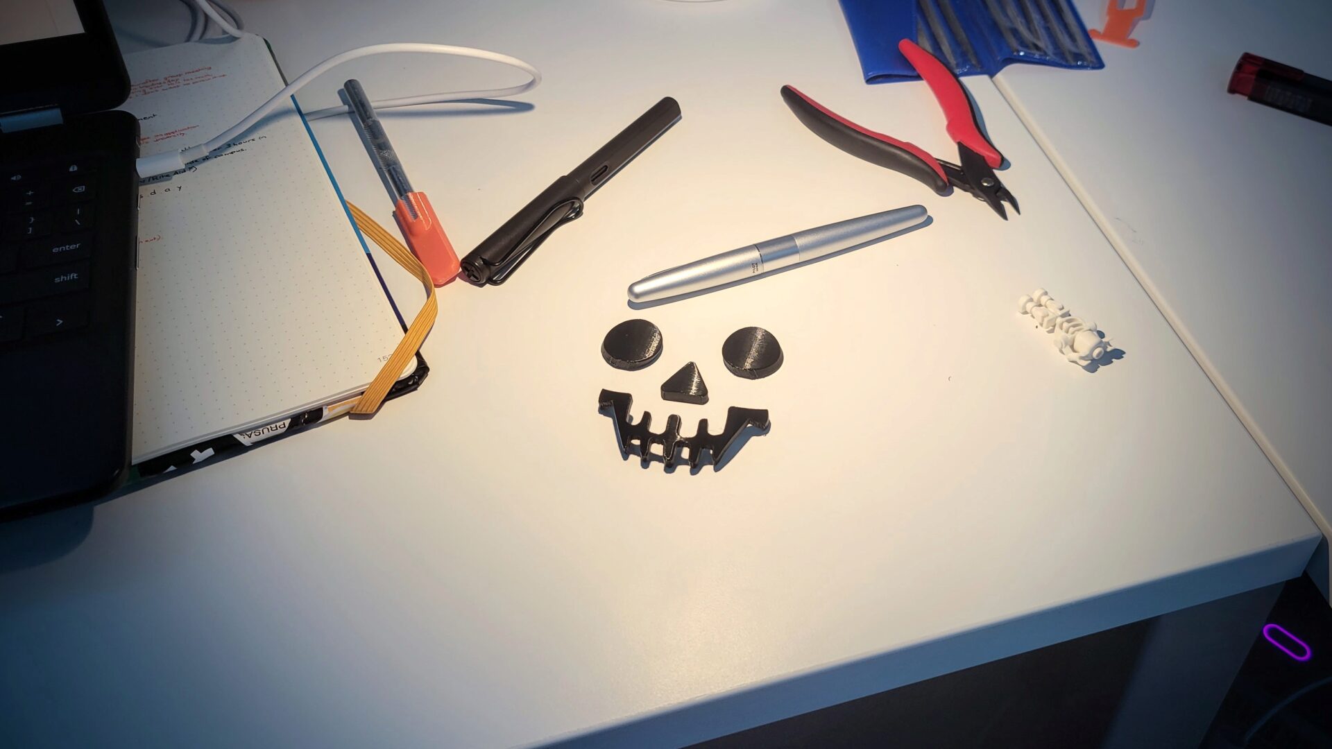
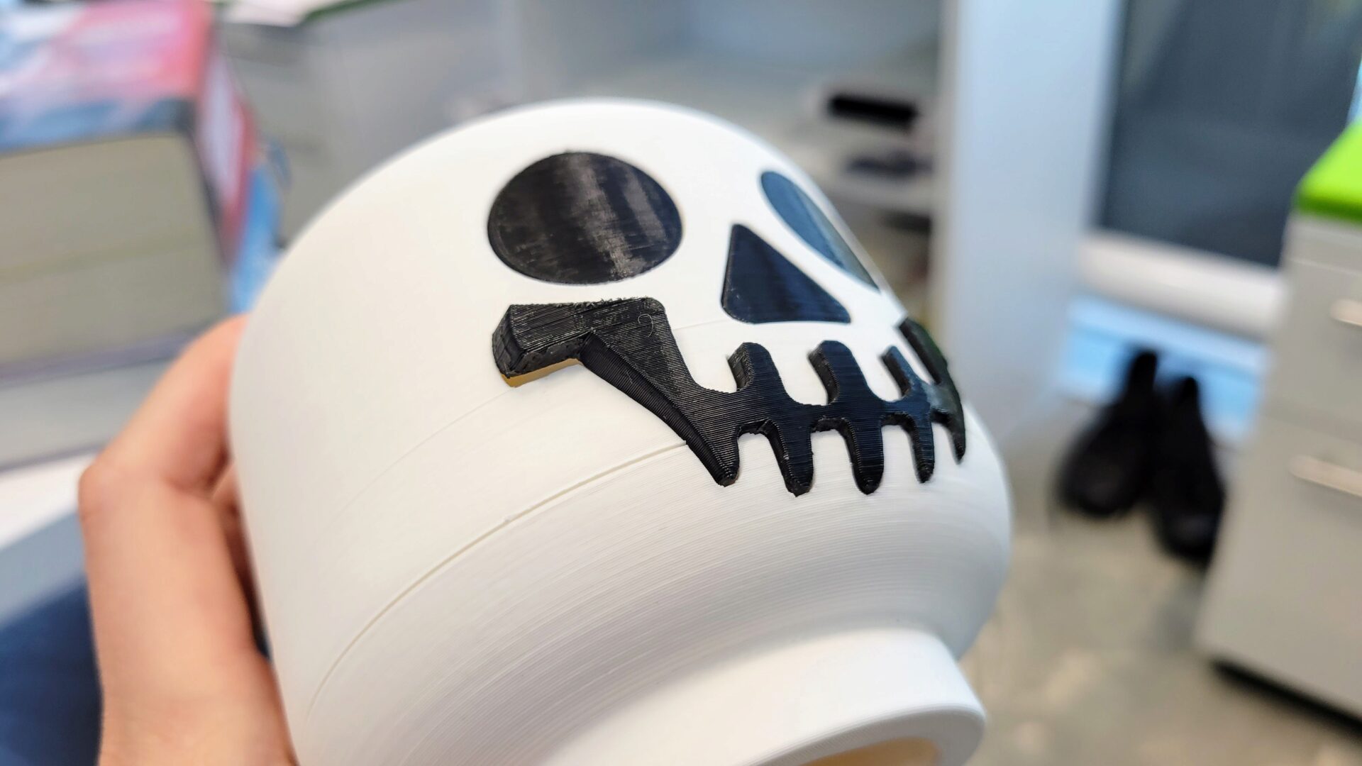
I’d already printed the face parts as well. Printing these pieces upright felt really weird, since there was so little bed surface contact, but it worked; nothing came off the bed, even the little bits of support material. Does it look spooky enough?
Skull Assembly
The last challenge, though, is actually putting the face into the skull. I’d given myself what I thought was a generous 0.2 mm tolerance on all sides, but that failed to account for the quirks of the print orientation. There was slight sagging on bridges, there was support interface material that didn’t want to come off, there were supports sucks to the supporting horizontal surfaces. And I didn’t think to add a chamfer to the backside of the face parts (even though I did remember this for all of the dowel pin holes!) With a bit of work with an Xacto knife and tiny files, I was able to force the eyes and nose into place. (They’re not even glued; it’s a tight press fit.) The mouth is another story. There are a bunch of little tiny features (by which I mean teeth) that required support material on both the black mouth part and the opening on the skull. My Xacto and file skills weren’t cutting it, so I decided to just reprint it with larger tolerances (0.25 mm instead of 0.2 mm), and with a chamfer on the back to help cram it into place.
It turned out that these changes didn’t help as much as I’d hoped. Because of the tight curve on some of the tooth corners, I was only able to add a 0.5 mm chamfer to the back of the mouth, which isn’t a lot when you’re already using a 0.4 mm nozzle. Increasing the tolerance by 0.05 mm was also very optimistic of me. I still ended up spending more time than I wanted with the files and Xacto knife, but at a certain point I declared it good enough. To this point, I’d been checking my fits without gluing together the skull, so that I could still get the tight mouth piece out (the split in the skull goes right through the middle of the mouth, on purpose).
Time to glue together the skull halves.
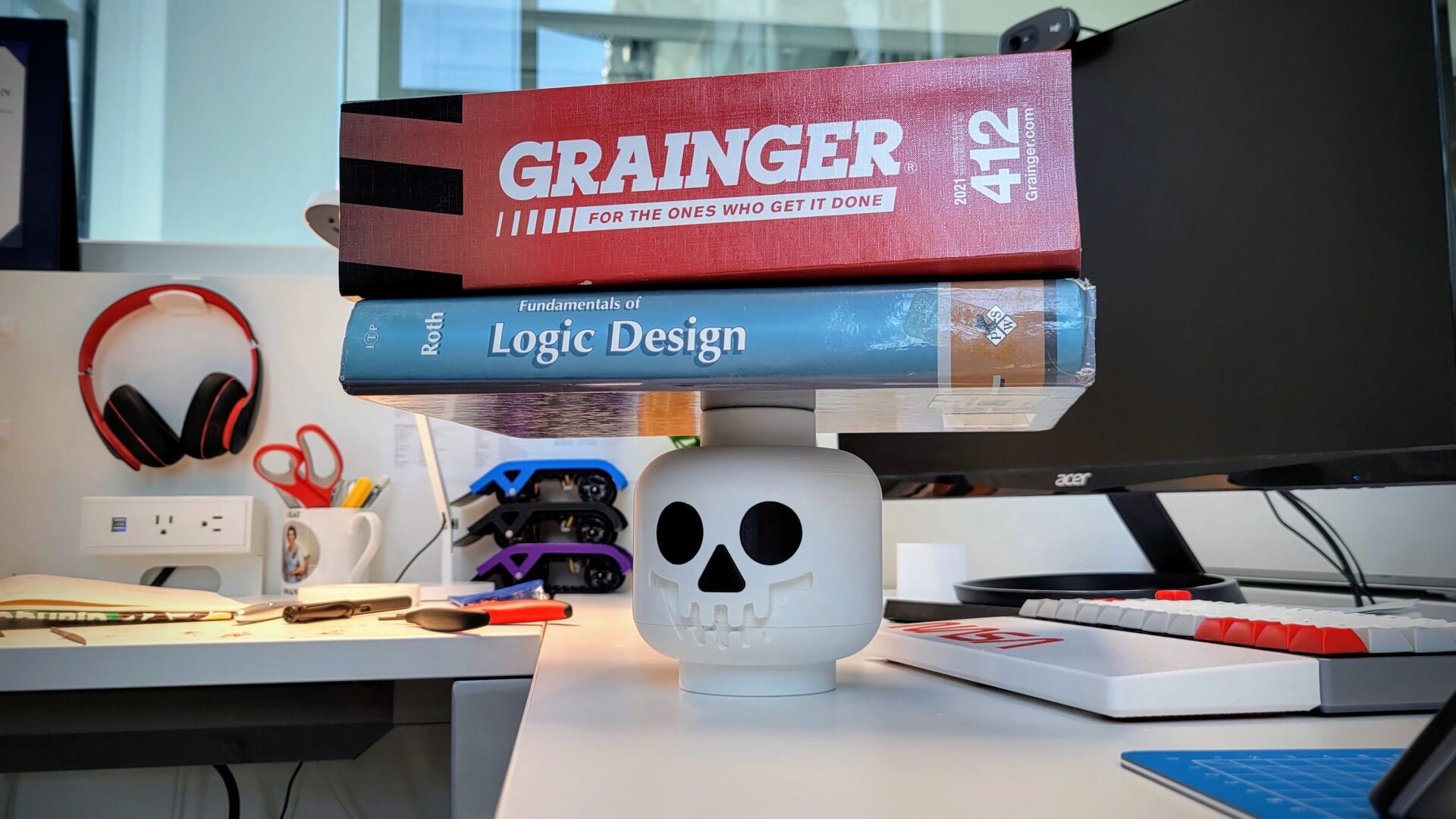
I used the highest-quality clamps: outdated textbooks and catalogs that normally serve as a monitor stand. There’s a tiny gap that’s noticeable between the two parts. I was able to squeeze this together by hand, but the top-of-the-head clamps aren’t able to exert pressure on the edges to close this up.
Once I was relatively certain that the skull glue had cured, it was time to force the mouth into place.
…crap. So close. I was able to pry it out with an Xacto knife (yes, I know that’s not safe) and file it down a bit more. To get it back in, this time I started with the corners of the mouth, which seemed to help it align better. Then there was a lot of brute force. I rolled it on the face with most of my body weight. But it worked.
Final Form
All that’s left is ceremonially placing the skull on the skeleton. It fits on perfectly: a nice press fit, and still relatively easy to turn the head if you want. It does make a horrible sound when taking it on and off, though, thanks to the layer lines crossing each other. We’ll just call that a Halloween sound effect – the screeching of the skeleton’s soul when you try to take its head away.
That was a quality use of a couple of weeks of free time. This is the biggest assembled 3D printing project I’ve done so far – both in terms of number of parts and absolute size. It was a nice foray into the world of 3D printing something bigger than my printbed, and I learned a lot about what to do (super glue and dowel pins) and what not to do (whatever I did with the mouth).
Next up: human-scale Lego skeleton? (Hit me up if you want to sponsor the absurd quantity of filament that would require.)