Creating a Keyboard
Posted: 2019 December 17
Last updated: 2020 February 3
- TL;DR: The current status
- Links & Files
- Inspiration
- Layout planning
- Designing
- Keycaps
- Firmware
- Making the case
- Assembly
- Programming
- How does this work?
- Bill of materials
- TODO
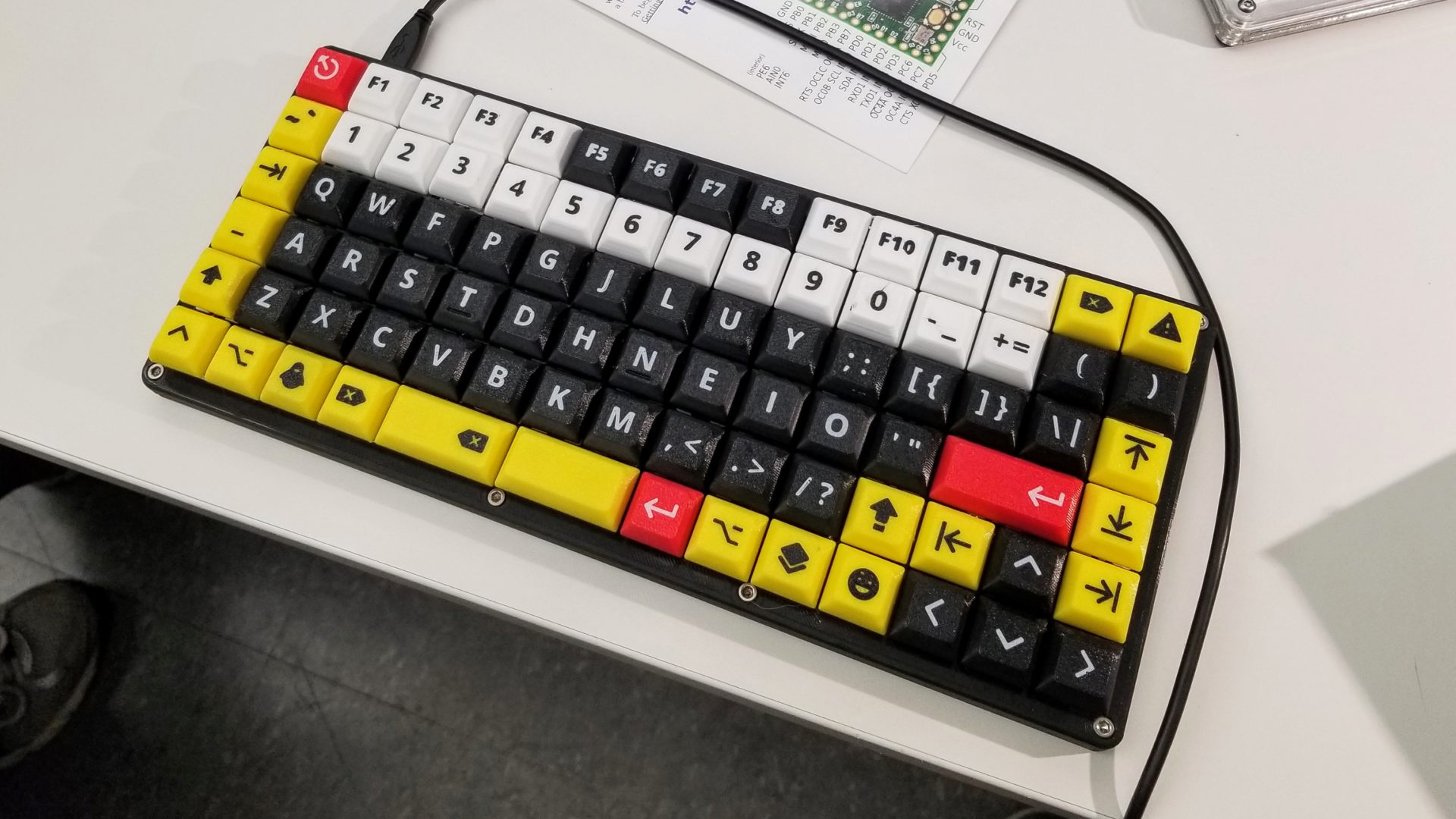
This is a build log of our ortholinear 87-key (~75%) keyboard as a class project for Physics 223.
TL;DR: The current status
It’s built! And it looks like the original render! And it works! Unicode now works, too (look, emoji: 🐄🐘🐕🐁 – see this update) but the caveat is that for the moment, the keyboard only works with a Colemak layout, but none of the unicode/emoji keys line up with where you’d want them to be relative to the letters. (Sorry, QWERTY plebians.) Don’t worry – it’s on the TODO list.
You can download the latest version of the firmware from the GitHub repository.
(Gotta put a nice picture first for the social media previews.)
Links & Files
Interested in making all or part of this? Here’s what you’ll need.
Firmware
This keyboard uses QMK, so it’s very flexible to modify the layout.
Firmware source files. And this project’s files.
To build the firmware (once you have your system set up), run:
make artemis75:default
Then flash according to the QMK instructions.
3D printed parts
These are the STLs as exported from the above source on 2020-01-15 (v1.0). If changes have been made to the source CAD since then, you can also export yourself. If you want to change the tolerances, you’ll also need to make a copy of the CAD document and modify it. At this point, I haven’t had time to clean up the CAD files to make it more clear what you need to do to make these changes. (I’ll hopefully get to that eventually.)
Case STLs
The case is 297 mm wide, so you either need a big printer, or you’ll have to split it into pieces to print.
Keycap STLs:
The keycaps are split into groups to print in the print area of a more normal-sized printer. I recommend printing the keycaps face down with a layer height of 0.1 mm. For more printing details, see the keycaps section below.
Assembly
Bill of materials for additional parts
Inspiration
I want to build a custom mechanical keyboard from the ground up. That means a custom layout, designing the case to fit that, hand wiring the keyboard, getting (or making) keycaps, compiling my own firmware,
Why? Possibly technological masochism? Also wanting to understand how a keyboard works and set it up just right for how I want it.
Why now? I want to see if I can use it as a final project for my electronics class. Plus, it seems like a great way to procrastinate on the thesis-related work I’m actually supposed to be doing. It’s a bit of an intimidating project, so this seems like a nice kick in the pants to do it.
According to this it takes a couple months and a couple hundred Euros to build a custom keyboard. I have a couple of weeks and no desire to spend hundreds of dollars. What could go wrong? On the other hand, I have quite a bit of experience with electronics (thanks to this class), programming (including C and microcontrollers), and I’ve built a keyboard before (albeit from a kit).
Design inspiration
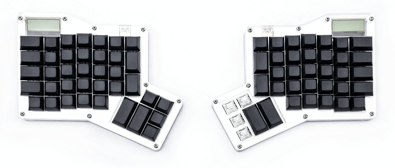
I like the ortholinear keyboard design of my ErgoDox Infinity keyboard.
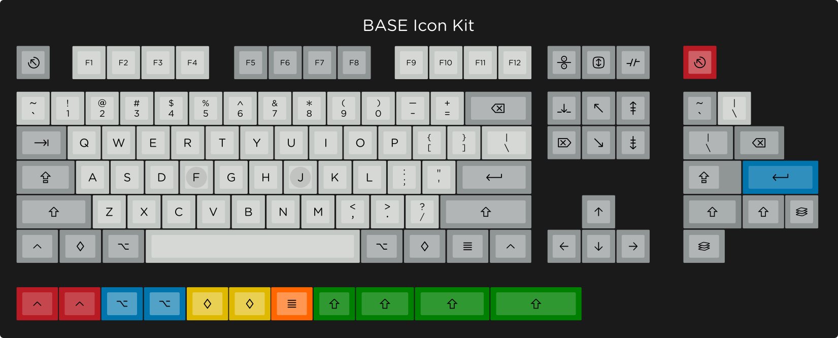
I like the icon keycaps of the Granite keycap set (but I’m way too cheap to ever buy it).
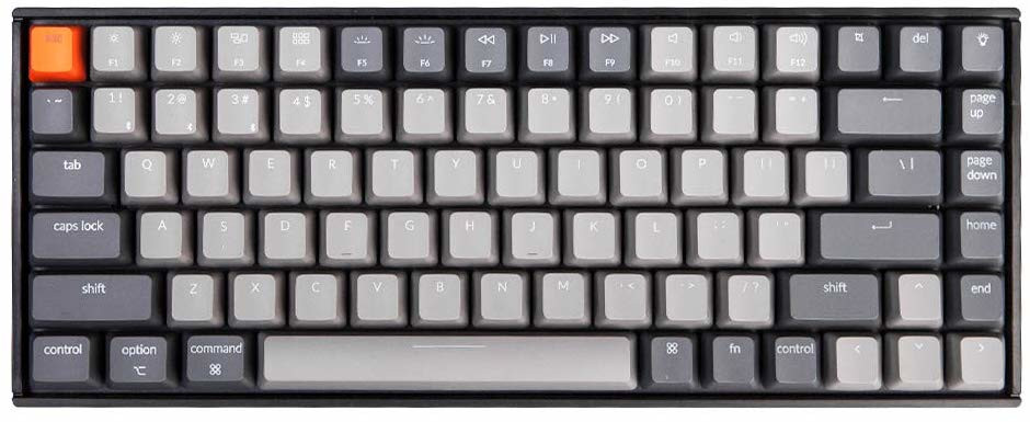
The 84-key size and style of the Keychron K2 keyboard seems like enough to have the useful stuff without keys I’m never going to use. Typically, this is called a 75% layout. It’s about the same number of keys a “tenkeyless” (TKL) keyboard, which is a full-sized keyboard with numpad, but it’s laid out in a more compact form factor.
3D printed keycaps (which I think I can make look nicer than this). I like the large legends, which should be easy to read when printed. (Link below.)
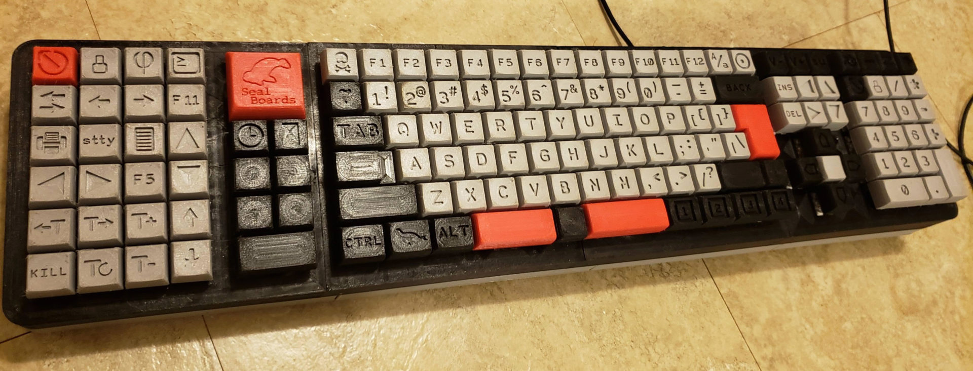
On a GeekHack thread, some people were coming up with ideas for full-size ortholinear designs.
And someone on Reddit actually made a 14x6 ortholinear keyboard, which commenters described as “enormous” and “What a beast.” But even the creator said that the 1u space bar(s) in this were a pain.
Useful tools and references
Electronics:
- Reddit links to tutorials/resources for handwiring keyboards
- Another guide, this one with good pictures and explanations. The result here is very clean-looking, and I ended up referencing it the most while wiring.
- Yet another hand-wiring guide
- The seemingly canonical keyboard-building guide from Matt3o
Case/keycaps:
- Someone made CAD files of DSA keycaps (and posted them on Reddit and shared a Google Drive folder) (EDIT: Now it looks like it’s based on Thingiverse)
- Someone else has a whole OpenSCAD system for keycap design on Thingiverse. Unfortunately, I suck at OpenSCAD and the whole thing seems rather poorly documented.
- SiCK-68: an open-source 3D printed keyboard with good documentation
- SMOLBOAT case: the ortholinear basis for the SiCK-68. It doesn’t seem to include much documentation - just STL files for the case(s).
- Someone made a fully 3D printed keyboard (including keycaps) (GitHub)
- SwillKB Plate & Case designer for getting the correct sizes to insert switches. (It’s designed for laser cutting. I could do that or turn it into a 3D printable part.)
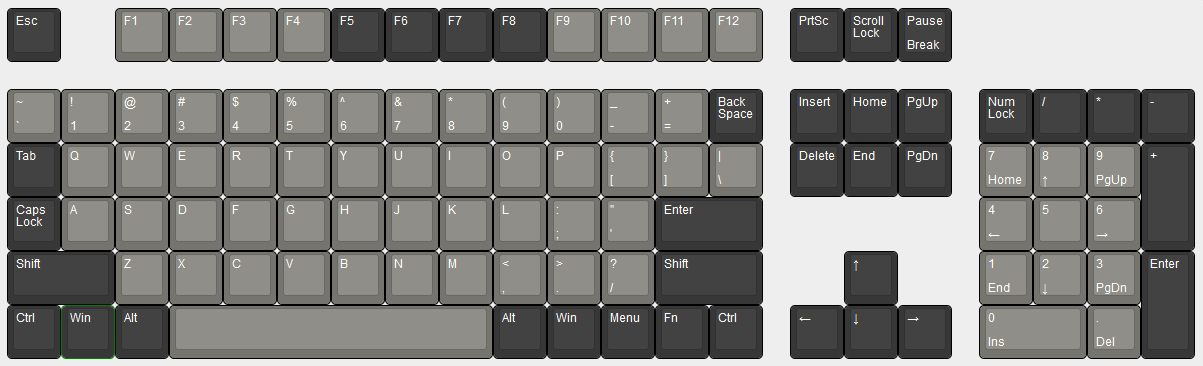
- keyboard-layout-editor.com, for designing the layout (which imports to the plate builder above)
Programming:
- Guide to building your own firmware (using TMK)
- Easy AVR: A GUI for designing layouts/firmware and flashing it
Layout planning
Based on the ideas above, I came up with this initial design:
It’s a 15x6 grid requiring a total of 84 switches.
I’ve added a number of customizations for my personal preferences:
- There’s no right shift key because I absolutely never use it. Instead, I’ve put a small caps lock key in its place.
- Where caps lock was, I now have an underscore key. I’ve done this to my ErgoDox keyboard and I love how convenient it is for programming. (Snake case FTW!)
- The space bar is split in half, with the left half becoming a backspace bar (stolen from the ErgoDox again).
- Currently the warning sign in the top right corner will probably function as print screen, but again – not locked in.
- The 4 lines key on the bottom row I’m planning as a function/layer key so I can add additional functionality (like controlling volume or opening the calculator) on the other layers.
Because I can always make new 3D printed keycaps and re-program the board, this also means I’m not locked into this layout forever.
This does involve a lot of custom keycaps/sizes, so I’ve basically given up on ordering something and decided I’ll design and 3D print my own. If I don’t get that done by the time limit for this as a class project, I can always slap on something from my pile of miscellaneous caps, even if it looks kind of trashy in the short term.
I’m definitely not set on the colors yet. But I do know I have (or have access to) black, white, red, and yellow printer filament. If I print in PLA, I’ll have more color options than if I use PETG, but the latter might make for higher quality keys. If you buy injection-molded keycaps, they’re usually ABS, but there’s no way I’m messing with printing that stuff.
Designing
As I start to look at keycap designs and stabilization, I’m realizing that my 3u space bar/backspace might prove difficult: it’s large enough that it should have some stabilizer, and 3u isn’t a standard keycap size. A pain to make keycaps, and one more thing I need to buy and design for. The easiest solution while keeping the whole thing ortholinear: make the space bar(s) 2u and add more keys for thumbs! From my experience with 2u keys for thumbs on my ErgoDox, that’s small enough not to need stabilizers.
I also realized my first design had the bottom row of letters shifted over 1u to the left from what my current setup is, which would inevitably drive me up a wall. So now I’m switching to hoping that a 1u shift key doesn’t drive me up a wall instead.
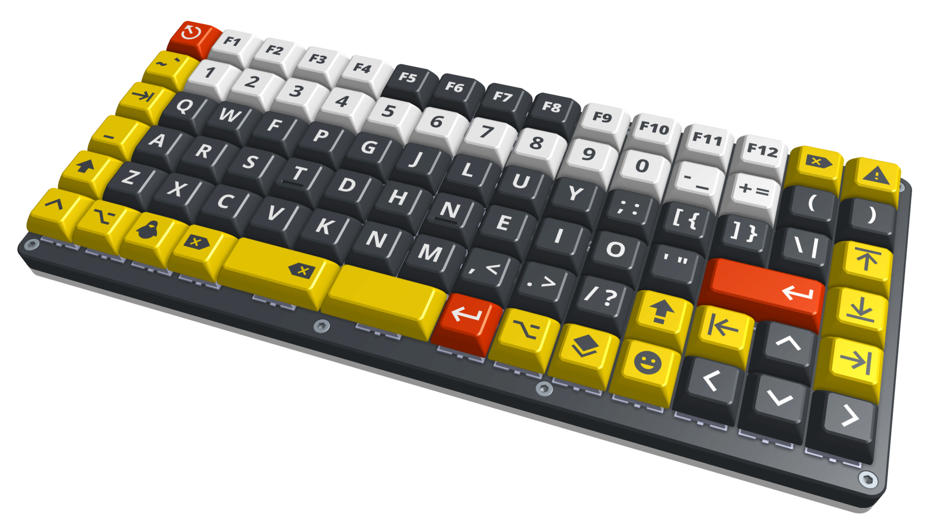
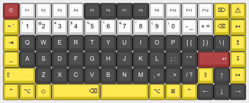
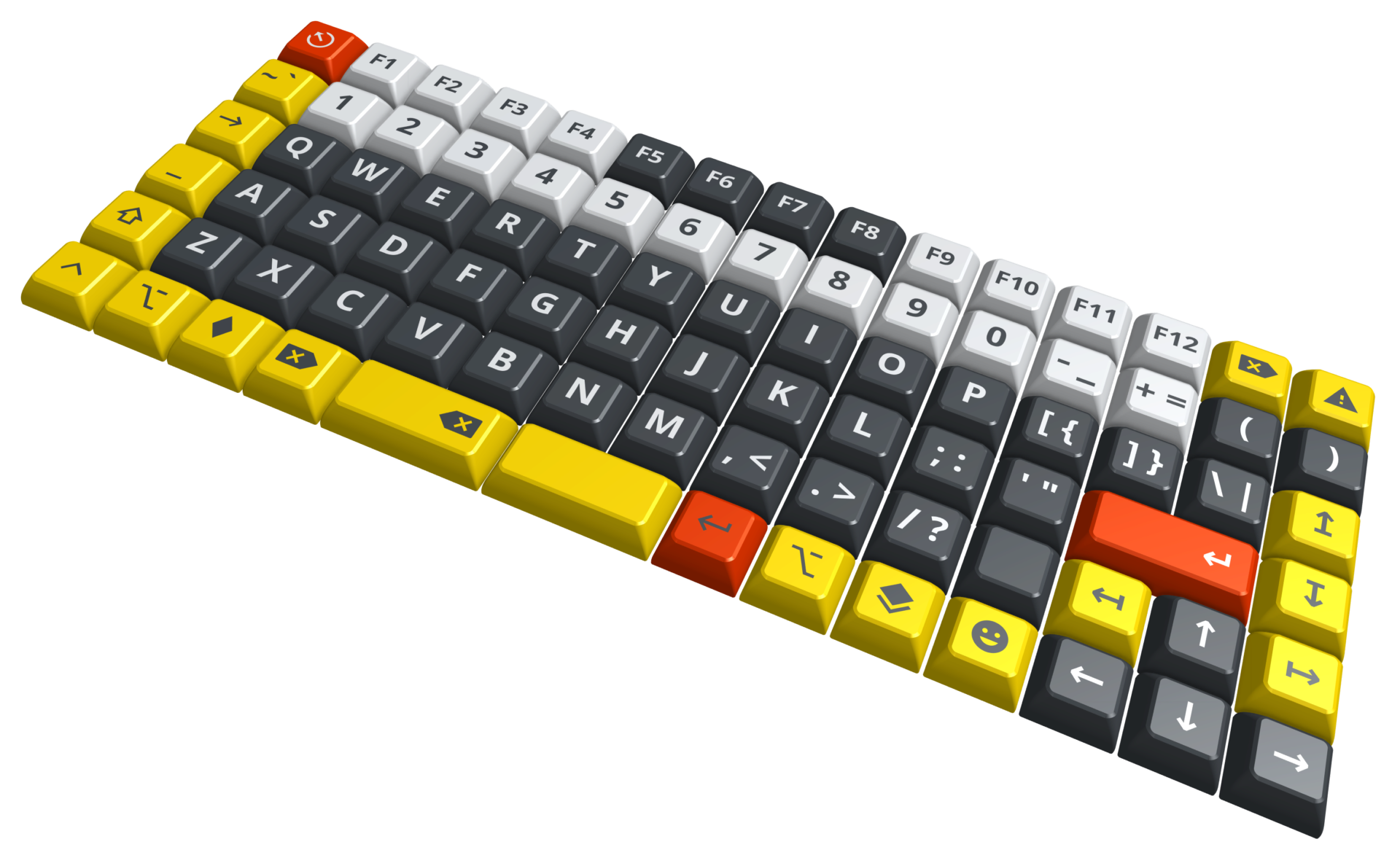
Which brings us to the updated layout, now with 87 keys (and made in Inkscape):
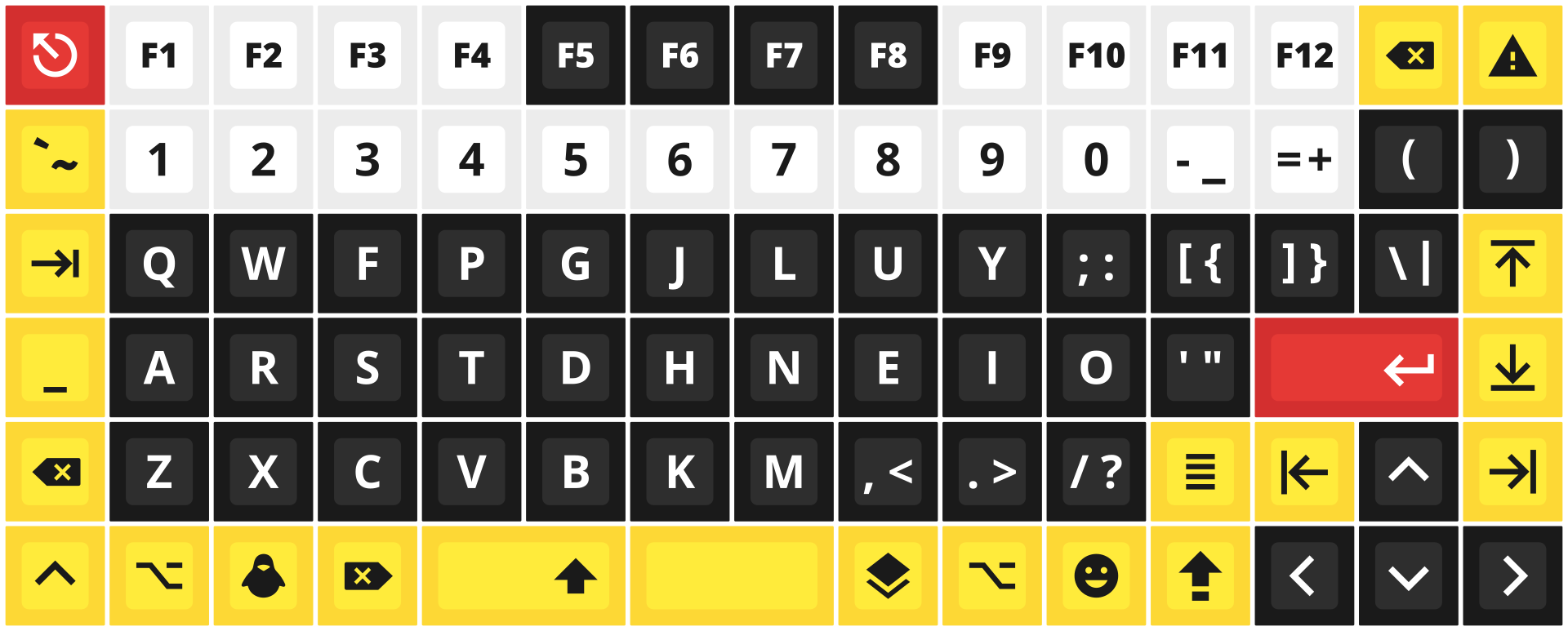
For pointless funsies, I also thought it would be fun to make a function layer just for emojis. Why? How about why not? Now I can more easily write Emojiscript.
(The emoji for the function role are basically a selection of random animals.)
And finally, I made an unnecessarily nice diagram of the wiring, without actually knowing if this will work.
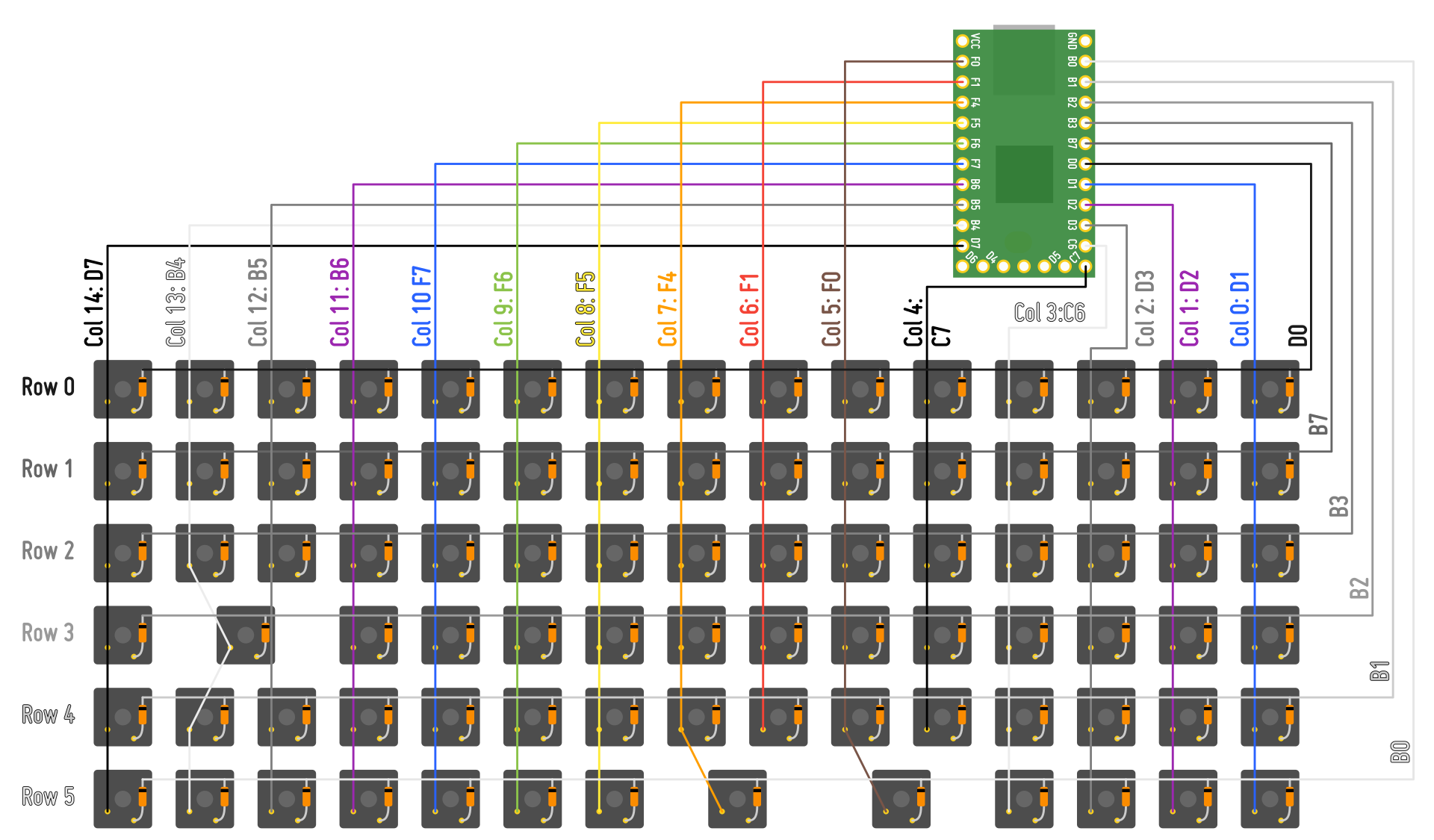
Note: to avoid confusing myself in the future, I’m updating this wiring figure to match what I’m actually doing. Trust me, the original still looked very similar.
Spend way too much Prednisone-fueled time in OnShape and I have a render of a first prototype!
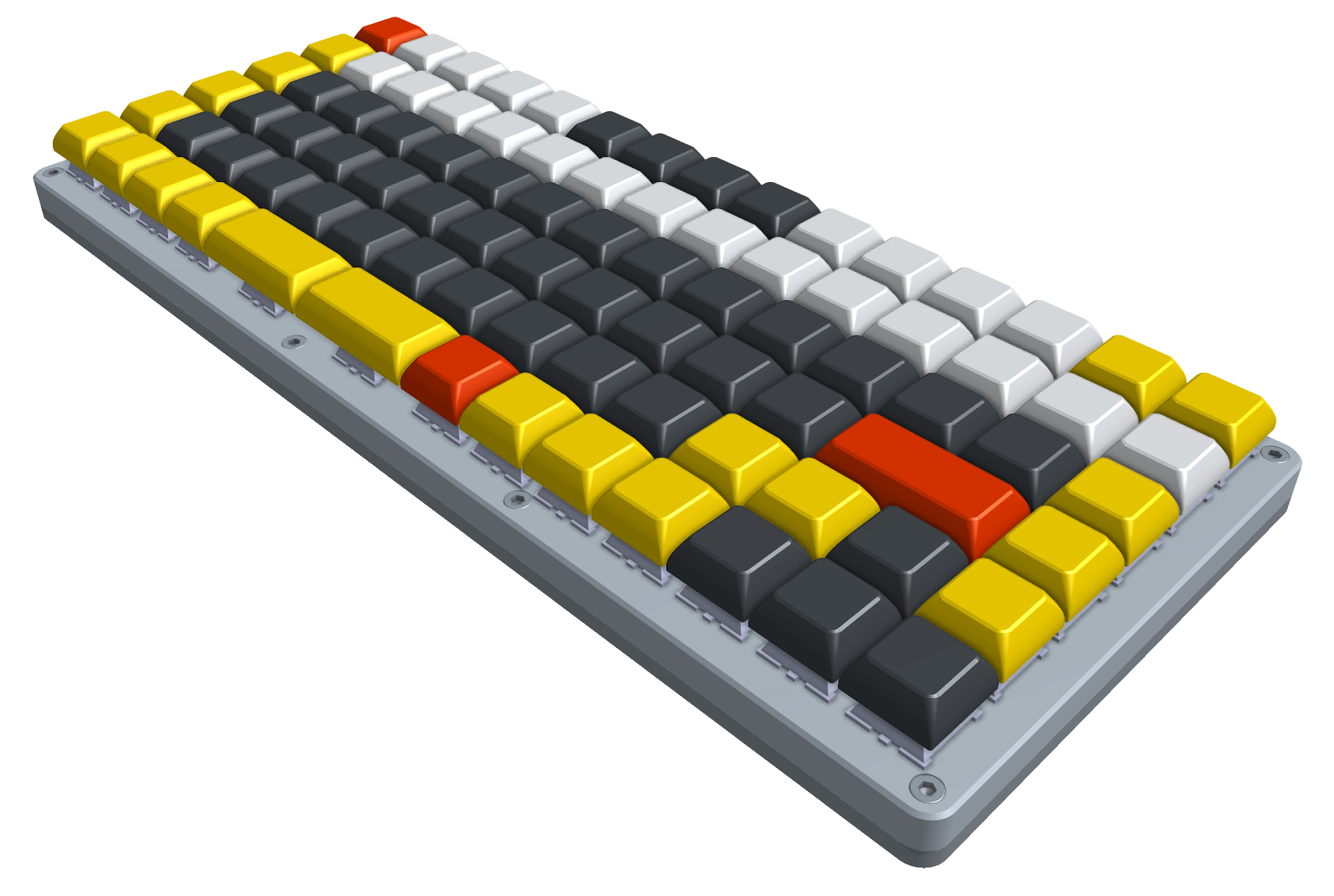
This completely neglects things like tolerances, since I haven’t printed pretty much any of these parts. But it looks nice, right?
The body is composed of two 3D printed pieces, each precariously close to the 300 mm length limit of Clark’s printer, clocking in at 297.7 mm. Each is designed to print with a nice flat base (with possibly a few minimal supports to hold up some holes for nuts on the bottom of the bottom piece.) In theory, this should also work with 10 mm M3 screws and not have them stick out the bottom, but I’ll believe it when I print it. (Also, no idea if this is enough screws for the whole thing to feel sturdy, or if it’s completely excessive.) Right now, the keys are all blanks, because I’m not going to waste my time designing the details of keycaps that possibly don’t even work. For the space for the Teensy, I blatantly stole the shape and dimensions from the SiCK-68 linked above. If it works, why reinvent it? (Though, I haven’t verified yet if it does work…)
Keycaps
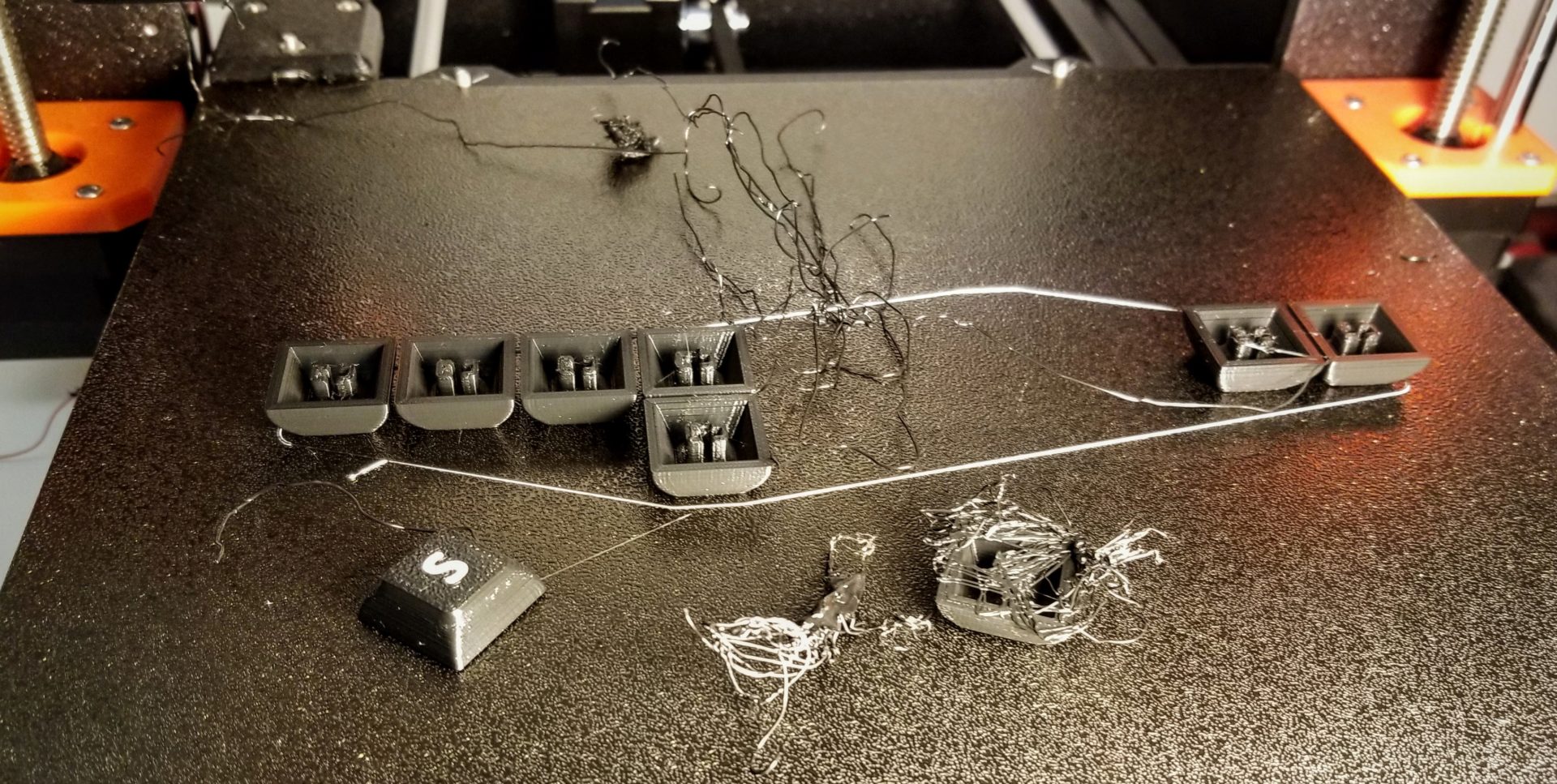
Meanwhile, I’ve also been working on the keycap design. Here’s a comparison of my first efforts.
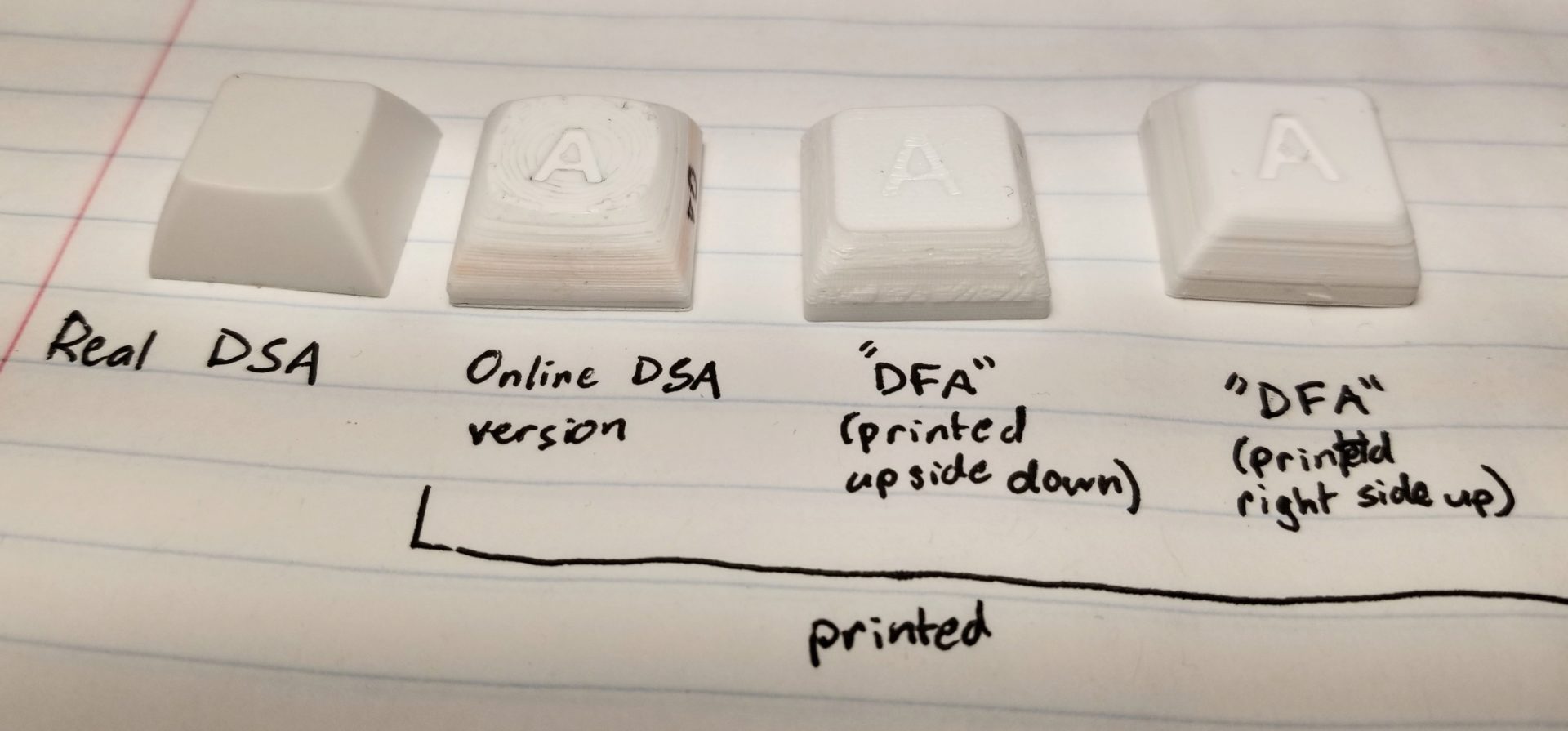
I printed everything in white to show off every flaw. Of course, they all look crappy compared to the actual injection-molded version. The first version I tried was the Thingiverse DSA keycap) (with the addition of my own imprinted legend). As expected, the biggest problem here was the gently curved top surface – it looks pretty topographical and quickly collects finger grease.
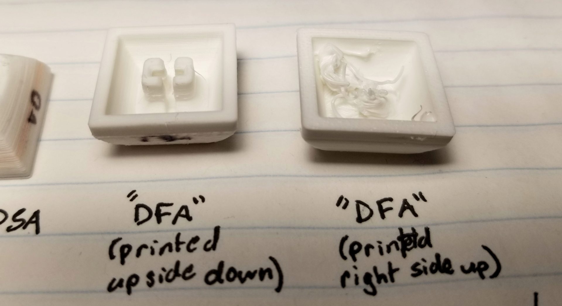
So next I made my own variant of this with a flat top. I measured some of the features in the DSA STEP file, made up the rest, and gave it a new name: DFA. Like DSA, but with “spherical” replaced by “flat.” So creative. My first attempt for this I printed with the top down, which I figured would give me a nice finish on the top. But I ran into two problems here: the first was that Attempt #1 came off the printbed halfway through the print, though from N=2 I can’t tell if this was just a fluke. But more problematic, the sloping side surfaces look pretty crappy. I was hoping that the gentle slope would mean it would get a nice finish despite the slight outward angle, but there are some really weird textured artifacts here. Perhaps my tiny 0.07 mm tall layers are biting me here. But if I switch to taller layer, the layer lines will be more prominent…
As a comparison, at least, I printed the same design with the top up. This time, the print technically finished. If you just look at it from the top, it looks pretty good! It could use a little work to minimize the dots on the top surface from retraction, and I probably need to slow it down or check my belt tension to get the sides extra smooth. But the bigger problem here is underneath: The stem for attaching to the switch came off the bed. It’s pretty cool that it even finished at all, but I should probably add some sort of manual brim in the future to keep that from coming loose.
The next step is to actually systematically test out an array of keycap tolerances to find what will fit sung on the switches without falling off or being unremovable. And I need to do the same thing for… the rest of the keyboard parts.
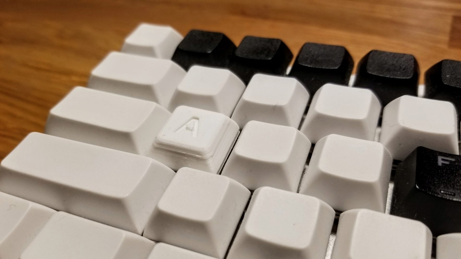
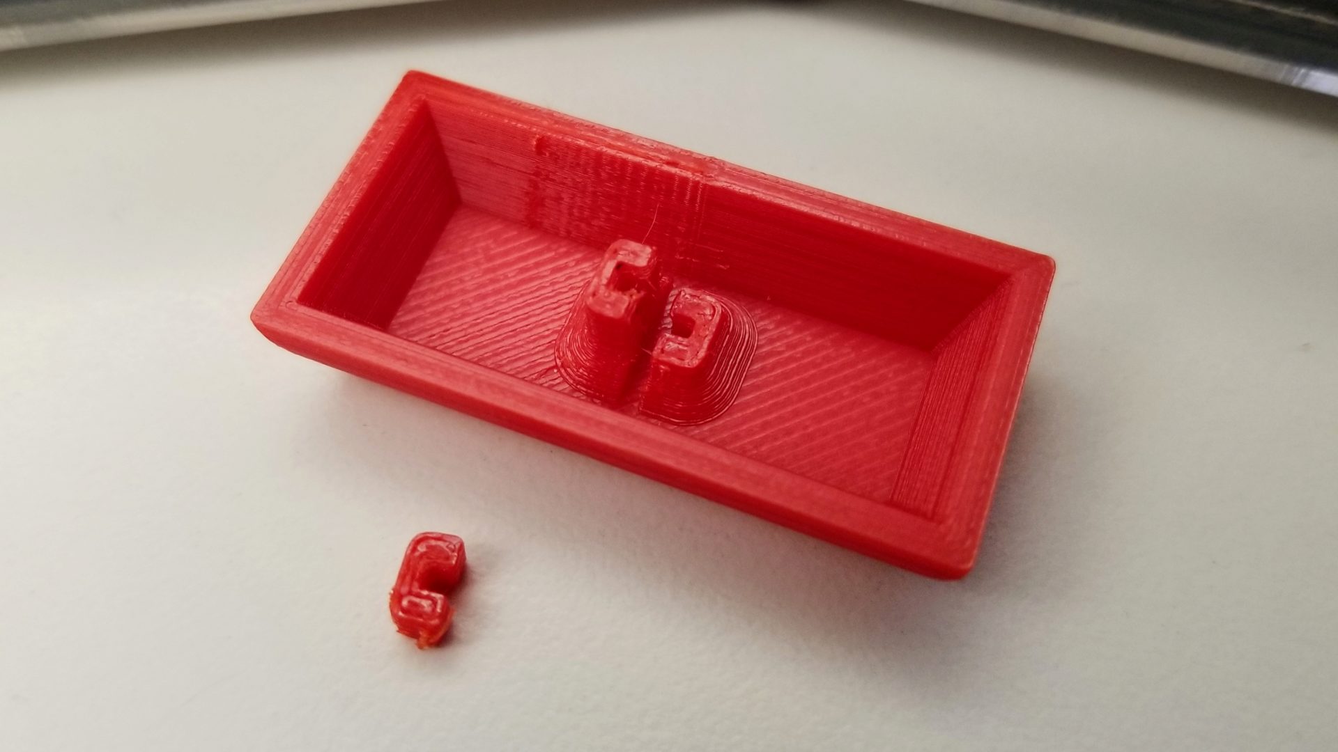
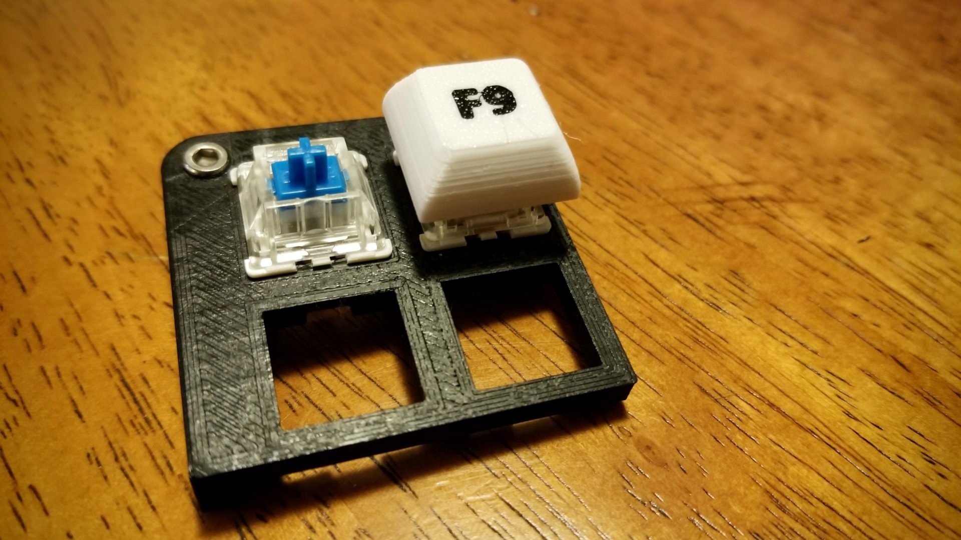
Coming back a week later, I did just that. First, I fixed the bed adhesion issue by adding a 0.2 mm thick bar connecting the stem part to the outer part. (I should probably just take a picture.) I increased my tolerance/slop factor to 0.15 mm, kept my 0.07 mm layer height, and bam – I have a functional keycap!
I’m still getting some weirdly prominent/funky layer lines, so I decided to try printing with a 0.1 mm layer height, keeping the same tolerance (and this time printing in black). The resulting keycap was so loose that it didn’t stay on the switch at all. I can’t tell whether it’s from the different filament color or the layer height, but at least the layers look a little bit nicer. Actually, the fact that this tolerance is now too loose for a taller layer height suggests that I was getting a bit of (probably inconsistent) over-extrusion for the thin layers.
I checked the inside of the cross for the stem on both the 0.1 mm and 0.07 mm layer prints (which is tricky to get calipers into) and it verified what I suspected: despite the larger tolerance, the lower layer height cap had a smaller opening. So I think we’re just gonna stick to 0.1 mm layers. So I printed out the caps with different tolerances:
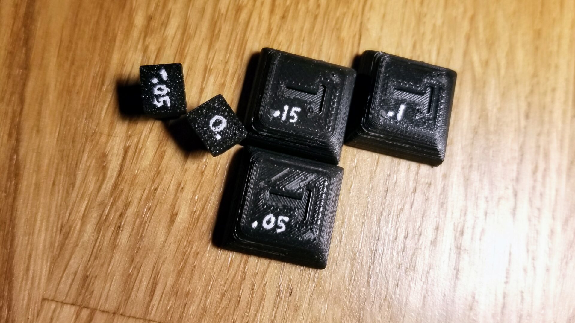
At some point I stopped printing the whole thing and saved myself 20 minutes each by only printing the stem portion. Because I kept having to go lower and lower. Eventually I settled on -0.05 mm, but I can’t say for certain whether this is actually negative, because I couldn’t find consistent information online about the canonical size of the “+”-shaped stem of Cherry MX-style switches. (And again, measuring this tiny thing with calipers is a pain.)
Making them prettier
Yesterday I ran across a Raspberry Pi Case on Thingiverse that took an interesting approach to creating multi-color prints without actually needing a multi-material upgrade to the Prusa. Basically, you change the filament manually instead of having the machine do it, which works fine as long as you don’t have many swaps to do. In the case of this case, there are one or two accent colors in the first layer that get swaps, and then the rest of it prints in the main color. I can definitely steal that and apply it to my keycaps. Here’s the setup process:
- In CAD, create the keycap with a 0.2 mm depth inset for the legend. (0.2 mm is the height of the first layer.) Make the legend as a separate part (in place), 0.2 mm thick. Export each as a separate STL.
- PrusaSlicer setup:
- Under Printer Settings > General > Capabilities, set the number of extruders to 2, and check the box for Single Extruder Multi Material
- For each extruder on the left side of the Printer Settings, change the color so you can tell them apart. In Printer Settings > Custom G-code > Tool change G-code, add
M600. That’s the code for manual filament change. - In Print Settings > Multiple Extruders > Wipe tower, uncheck the enable box. (You don’t need a purge block if you’re changing the filament manually.)
- Under Print Settings > Skirt and Brim, set the skirt height to at least 2. This will keep any gunk from the filament swapping out of the print itself.
- The Thingiverse link also has suggestions about post-processing to know which filament to swap when, but I haven’t bothered with that. You can tell which color will print first by looking at the color of the first layer skirt. If it’s not doing it in the order you want, just swap which STL is printed with extruder 1 and 2.
- Import both STLs at the same time. Because you have multiple extruders selected, you should get a prompt asking if you want to treat it as one multi-material object. Select yes.
- In the plater, check the right side bar and verify that each part is set to use a different extruder. Hit “Slice Now” and you should see the multi-color g-code preview for printing.
Surprisingly, this worked for me on the first try. I went back to printing the keycaps letter-side down for two reasons: first, I thought it would make a nice textured finish with the two colors (no bridging for the legend now). But more importantly, I could do the filament swapping immediately and not have it wait around for me half and hour (or more) later.
It looks sweeeeeeeet! And the top texture is so much nicer to type on than printing the keycaps right-side-up and getting those retraction bumps.
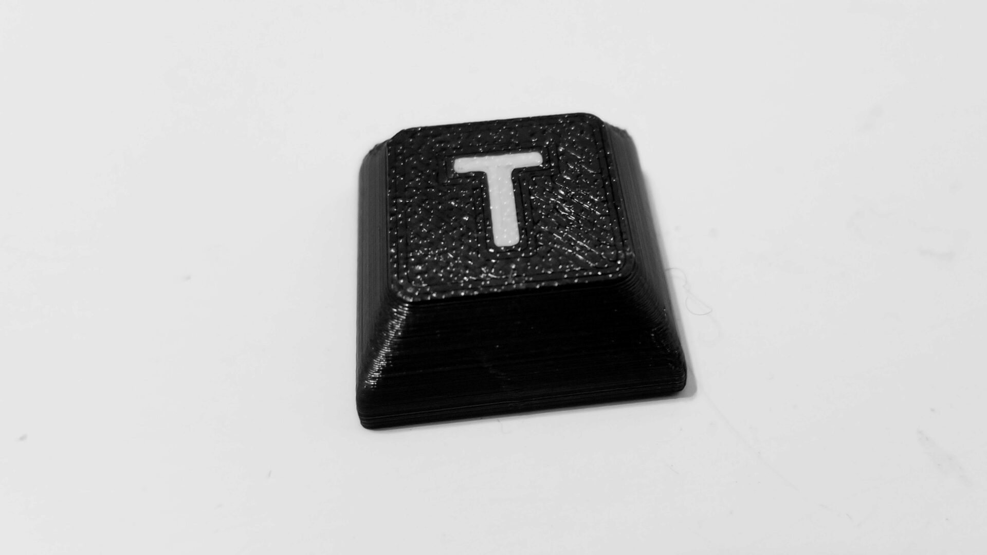
It’s not perfect, especially around the corners, but I think with a little fiddling with retraction and the seam position, I can get it looking even nicer. And if all also fails, I’ll just orient it so that part ends up in a less visible corner of the keycap.
(Update: I realized that this is occurring because of cooling. This only happens on the back corners because they’re on the opposite side of the fan. So I’ll just orient my parts that way.)
Now, instead of going to sleep, I can make the CAD for all of the keycaps. I’d been pondering the best way to do this for awhile. Should I try to manually type all the letters into a sketch in OnShape? And then import the icon ones as DXF files to put on each individual keycap? My instincts said this was a terrible idea and would make me sad. But I realized that I’d actually done pretty much all the work in the Inkscape render of the keycaps (see above). I could just export this as a DXF (after converting the text to paths) and use that directly.
The remaining piece then, was to generate the correct grid of keycaps to paste my DXF on top of. This I did kind of hackily. In a new part studio, I imported one 1U keycap and did linear patterns to make a grid. Then I imported the 2U keycap and did manual transforms to place them in the right location. Still better than recreating the whole legend by hand. OnShape definitely started to struggle with what I was throwing at it by this point – once I generated the inset pieces for the legends, I was at 209 individual parts.
After that, it was some quick recoloring, and I can actually render the full keycap set with legends!
Still a little inconsistent on when I’m using text vs. icons, and some of the colors and line thicknesses, but it’s relatively easy to change. I just make the change in Inkscape, export, and import into OnShape.
Making all the keycaps
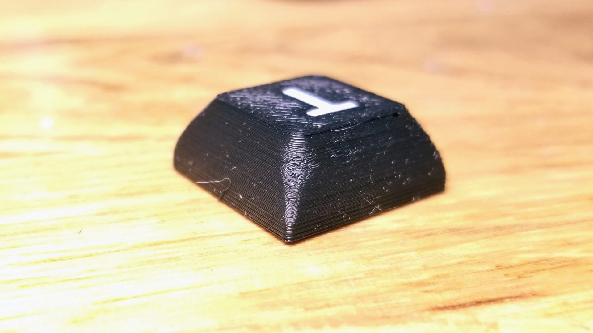
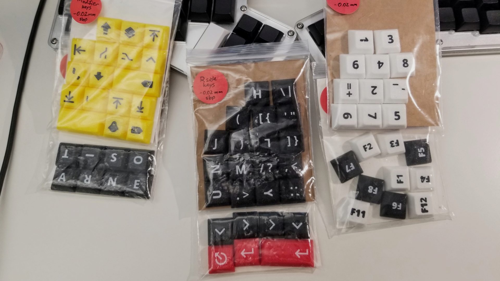
Once I started printing keycaps in batches instead of individually, I ended up having to change the tolerances again: -0.05 mm was too tight because the layers had more time to cool before the extruder returned for the next layer. The keycap stem attachments ended up being too tight. With a bit of force, I could still get them onto the switches, but then this happened sometimes when trying to get them off.
At least it just broke the keycap (which I can easily replace) instead of the switch itself. I did a bit of fiddling with parts of the stem design (reducing the asymmetry between the slot sizes for the stem) and increasing the tolerance to -0.02 to get something that worked for large batches.
The first set of multiple keys I printed was my highlight keys (because there’s red filament in the lab but not at home). Here’s a comparison of my three roundsto get them looking like I want:
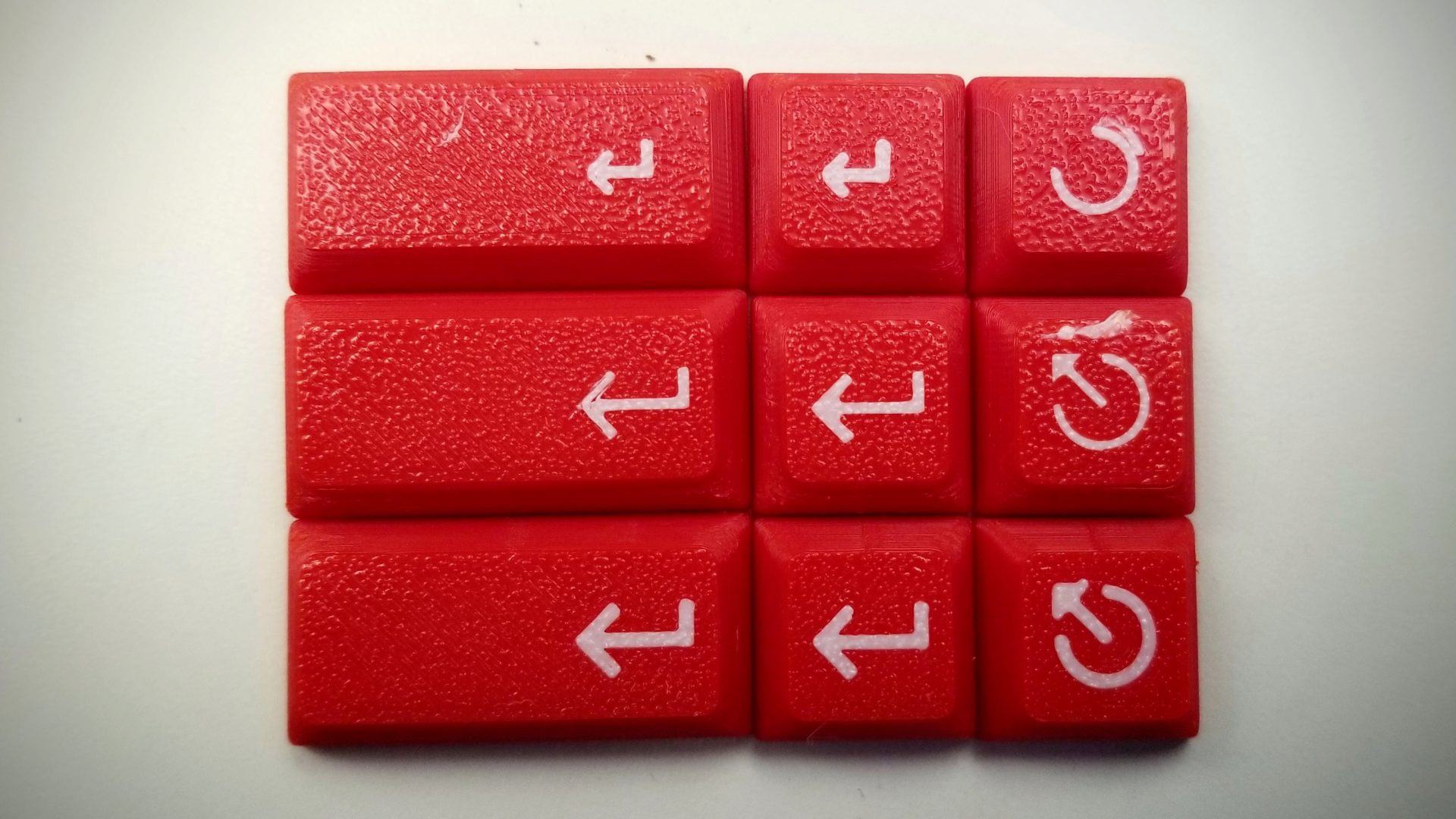
In the first version (top row), I was still using the text version of the enter symbol. It looks a little small and didn’t quite match the style I wanted. And the escape key symbol (also the text version) was smaller than I wanted; in fact, the arrow part came off the bed and just became a blob.
In the second version (next row), I switched to icons. The enter symbol is from the material design icons, and the (now also larger) escape symbol came from The Noun Project. In this case, it printed the red first, then filled in the white icons. This resulted in the icons coming out smaller/narrower-lined than I wanted. Because the first layer is always a little more squished and therefore produces wides lines than it should, whichever color goes down first will be on the bottom and look fatter.
So for the third version, I printed white first. Looks good enough for my purposes!
Now check out how many keycaps I made instead of studying for this final exam:
I haven’t had a 100% success rate with the printing. Occasionally they’ll come off the printbed (the bottom surface is pretty small, and I sometimes forget to clean the bed with isopropyl alcohol before I print). And a few have had some under-extrusion on the bottom layer, so the legends don’t come out looking very clean. I’ve had to reprint under 10 keys for the whole board.
#NailedIt. I let it keep going so I could at least get 7/10 keycaps out of that batch.
Firmware
From my cursory search, there seem to be two common approaches for programming a Teensy 2.0 as a keyboard: TMK and EasyAVR. In keeping with this class using low-level coding, it seems like TMK is the right choice, since EasyAVR is a GUI interface meant for non-technical people. And what fun is that??
I started by playing around with the keymaps, looking at part 2 of this tutorial and the TMK keymap documentation. (We’re still waiting on the parts to arrive, so this seems like a better place to start than messing around with setting up the pins.)
This shows how it’s very straightforward to set up the “standard” keys: alphanumerics, modifiers, and even system things like volume control and power. But for other things, it gets hairy fast. The first not-so-simple thing is setting dedicated keys for underscore and parentheses. The TMK documentation calls these modified keys – a modifier plus a key. An underscore, for example, is just Shift + -. So according to the documentation, that’s ACTION_MODS_KEY(MOD_LSFT, KC_MINS).
…But this documentation isn’t really clear on where on earth you’re supposed to put that line of code. (I could go on such a rant about documentation that makes very frustrating and off-putting assumptions about its users. Give examples, people!) From this other part of the documentation, it looks like you just use it directly in place of a keycode in a KEYMAP.
…But then I ran across multiple random forum threads like this and this, which seem to say otherwise. Here, they set that key to be an unused Fn key (e.g., FN8), and then within fn_actions[], they set that to be something like [8] = ACTION_MODS_KEY(MOD_LSFT, KC_MINS). That’s way uglier. And based off of this section of the keymap documentation, you can only have 32 function keys. If that’s really the case, the emoji layer is probably dead. (Also, based on this FAQ, it seems like there’s not even a universal way to implement unicode input; it’s OS-specific.) Even my current modifier layer has about 40 custom keys.
Long Live QMK
After looking around more, it turns out that there are way better options than TMK. As fork of it has since taken off and become its own thing: QMK. And QMK has way better documentation and more features, like native (software-based) support for unicode. So let’s use that instead. As a bonus, when you get it working, you can submit a pull request (even for your homemade, handwired keyboard), and they’ll include it in the repository so other people can make it!
But that means we first have to go through the process of creating a custom layout for a hand-wired board. I followed the instructions for “Creating and compiling your firmware locally (command line method),” because why would I do it through an online GUI when I can dig into it myself? (Maybe I’m old and just don’t trust the internet, but I also like to be able to keep track of everything in a git repository.) But the process was pretty well-documented and straight-forward (summarized here):
- On GitHub, create a fork of the QMK firmware repository.
- Clone your newly forked repository and create a new keyboard project with:
.util/new_keyboard.sh(and follow the prompts) - Navigate into the new project:
cd keyboards/<project_name> - In the project’s
config.hfile, fill in the number ofMATRIX_ROWSand MATRIX_COLUMNS`, pins that are used for each row and column (these should be in order) and any unused pins (to save power). Mine looks like this:/* key matrix size */ #define MATRIX_ROWS 6 #define MATRIX_COLS 15 ... #define MATRIX_ROW_PINS \ { F7, F6, F5, F4, F1, F0 } #define MATRIX_COL_PINS \ { B4, D7, D4, D5, C7, C6, D3, D2, D1, D0, B7, B3, B2, B1, B0 } #define UNUSED_PINS \ { B6, B5, B4, D6 } - In
<project_name>.h, we’ll fill out theLAYOUT: how the pins map to the layout of the keyboard. This I found a little confusing, because the example used key names likeK03for the key in the 0th row and 3rd column. But I have more than 10 columns. Because downloading the QMK firmware also includes the firmware for every other keyboard, I could look for examples of how othershandled it, and they weren’t consistent. Some usedk0A(hex) to indicate being the 0th row and 10th column, where others usedK010. (Also inconsistent capitalization.) These are all using constants/variables, not strings, so my guess is that behind the scenes QMK gives you every option, or some of them are aliases for others. I opted for the 3-digit version, which compiles; we’ll find out later if it actually works correctly. Mine ended up looking like this:#define LAYOUT( \ K000, K001, K002, K003, K004, K005, K006, K007, K008, K009, K010, K011, K012, K013, K014, \ K100, K101, K102, K103, K104, K105, K106, K107, K108, K109, K110, K111, K112, K113, K114, \ K200, K201, K202, K203, K204, K205, K206, K207, K208, K209, K210, K211, K212, K213, K214, \ K300, K301, K302, K303, K304, K305, K306, K307, K308, K309, K310, K311, K312, K314, \ K400, K401, K402, K403, K404, K405, K406, K407, K408, K409, K410, K411, K412, K413, K414, \ K500, K501, K502, K503, K504, K506, K508, K509, K510, K511, K512, K513, K514 \ ) \ { \ { K000, K001, K002, K003, K004, K005, K006, K007, K008, K009, K010, K011, K012, K013, K014 }, \ { K100, K101, K102, K103, K104, K105, K106, K107, K108, K109, K110, K111, K112, K113, K114 }, \ { K200, K201, K202, K203, K204, K205, K206, K207, K208, K209, K210, K211, K212, K213, K214 }, \ { K300, K301, K302, K303, K304, K305, K306, K307, K308, K309, K310, K311, K312, KC_NO,K314 }, \ { K400, K401, K402, K403, K404, K405, K406, K407, K408, K409, K410, K411, K412, K413, K414 }, \ { K500, K501, K502, K503, K504, KC_NO,K506, KC_NO,K508, K509, K510, K511, K512, K513, K514 } \ }- The first part of
LAYOUTis a 1D array containing all of the key names (just formatted to look nice) - The second part is a 2D array showing what key is in what row and column. If there’s a column without a key in that row (matching your actual wiring), it gets the code
KC_NOto make sure the vertical alignment of columns is retained.
- The first part of
- Now we can set up the keymap in
keymaps/default/keymap.cThis is where you assign what physical key maps to what character. For all of the “standard” keyboard keys, there are keycodes listed here. In addition to standard keys (alphanumeric, system keys), I also needed to encode my unicode (more on that below) and stuff like(as a non-shift key, which I explain below. - Now we need to compile. First (and not in the documentation) you need to run
make git-submodulefrom the repository root folder to install/compile dependencies. (Otherwise you’ll get an error about LUFA.) Then just runmake <project_name>:defaultto compile the default layout. (Or fix any errors.) If you have a mismatch anywhere in terms of number of keys specified for a layout/keymap, it will conveniently tell you when it fails to compile.
Special keymap stuff
Because it’s large, you can see the full keymap in my GitHub repository. But there were a couple particulars that I had to sort out to get the layout as I wanted.
Modifier keys (( = Shift+9): While TMK made this a pain, QMK makes it easy (as described here). Where I would but a keycode like KC_9, I instead use LSFT(KC_9) or S(KC_9) to get a left parenthesis (Shift + 9).
Emoji (full unicode mapping): QMK has a whole section of documentation for Unicode input. If I only wanted “simple” unicode characters (anything with a 3-4 digit code, which cover non-emoji stuff), there’s a simpler way to do this. But since I want Emoji (5-digit unicode characters), I have to encode all of my Unicode using the more complicated method.
- First, in the project’s
rules.mk, you add the following:UNICODEMAP_ENABLE = yes - In the
keymap.cfile, you then need to create names for every unicode character you want to use (before you define your keymaps):enum unicode_names { BANG, IRONY, SNEK }; - Then you add your map from names to characters:
const uint32_t PROGMEM unicode_map[] = { [BANG] = 0x203D, // ‽ [IRONY] = 0x2E2E, // ⸮ [SNEK] = 0x1F40D, // 🐍 }; - Now you can use these names in your keymap like you would any other keycode like
KC_9
Unicode strings: It turns out flag emoji are multiple characters, and I had decided to ironically put the US flag in the keyboard’s emoji layer. This multi-character part means that you can’t use the approach above to include a flag. Instead, you need a unicode string. This requires a couple of pieces in the keymap.c
- In the
custom_keycodesarray, add a name for your character (in my case,US_FLAG):// Defines the keycodes used by our macros in process_record_user enum custom_keycodes { ... US_FLAG }; - In the
process_record_userfunction, add a case to the switch statement for this character:bool process_record_user(uint16_t keycode, keyrecord_t *record) { switch (keycode) { ... case US_FLAG: if (record->event.pressed) { send_unicode_hex_string("1F1FA 1F1F8"); } break; } return true; } - Now you can use that character name as a keycode in your keymap
Switching unicode input mode: As I mentioned earlier, unicode is a PITA for keyboard input because different operating systems have different input methods. Luckily, QMK also has a way to handle this. It has a keycode for switching the unicode input mode, which is then saved to EEPROM. It’s kind of hacky, but I don’t know what a better solution would be. At least it’s easy to set up.
- In the keymap’s
config.h(<project_name>/keymaps/default/config.h) (not the project config file), add the following:#define UNICODE_SELECTED_MODES UC_LNX, UC_OSX, UC_WIN, UC_WINC(and remove whatever options you don’t want).
-
In
keymap.c, in one of your keymap layers, addUC_MODas a keycode, which will cycle through the input modes you specified. I have mine set toEmoji + Tab. - Unicode strings (flag)
- Switching unicode input mode
Reset key: My physical keyboard design (ingeniously) makes it impossible to get to the reset button on the Teensy when the keyboard is assembled. (That’s part of the design that I stole from the SiCK-68.) But QMK lets me set a keyboard key to do this! It’s dead simple: just use the keycode RESET for a key. (Mine is the top right key on the function layer.)
Making the case
Prototype
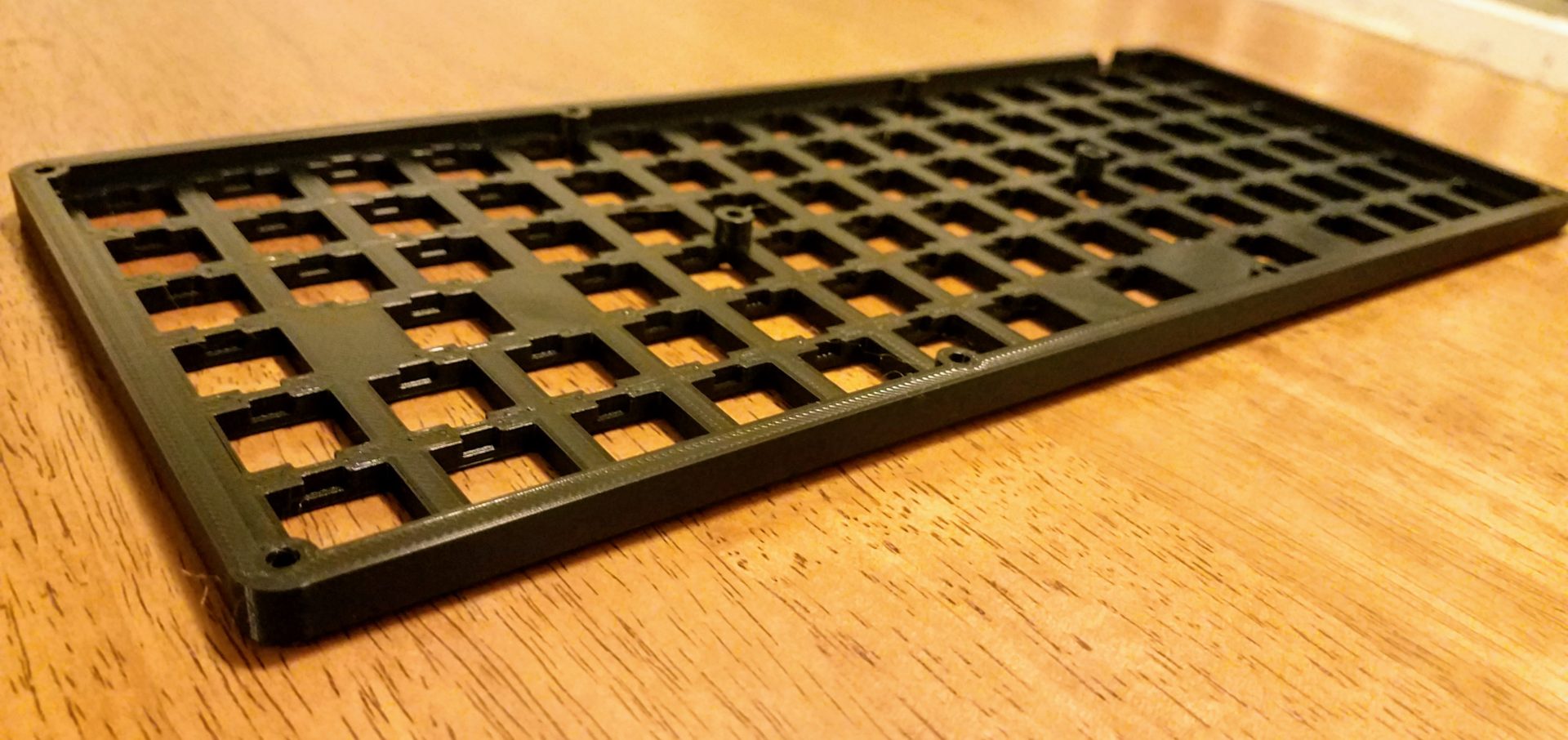
All of this needs to go into something. We can’t even wire anything until the case is printed – the switches have to get inserted into the top half of the case, and then the hand wiring is done on the backside of that. The challenge here is that the case is 298 mm wide, and my printer bed is only 250 mm wide. I could figure out how to split it up into pieces that I could glue/screw together after the fact, but luckily I don’t have to; my boyfriend Clark has a CR-10S printer with a 300 mm x 300 mm bed. The case will just barely fit in that. Nice.
Because every printer has different tolerances, I had to also test my case tolerances on that printer before I went ahead and printed the whole thing. So I cut out one corner of both pieces of the case and printed those (taking only an hour and a half of print time total). There were a three major things I needed to check the tolerances for: the M3 screw + nut, the switches, and the Teensy. I also wanted to see how my choice of colors looked: black PLA on top and natural/clear PETG for the bottom (hoping to somewhat show off the multi-colored wiring). It was printed at 0.15 mm layer height for a compromise between aesthetics and strength.
The CR-10S has a glass bed instead of the textured PEI I’ve been using for my keycaps. And we have to cover the whole thing in gluestick to get the PLA to stick to the bed (which, fortunately, can be washed off with soap and water). So the top surface finish isn’t as nice, but it will mostly be covered up by the keys anyway.
The switches fit into the case, but just barely; they were very difficult to get out. I increased the tolerance on the 14 mm square holes from 0.05 mm to 0.1 mm. At least the thickness of the top plate part was right (set to 1.5 mm and came out as 1.44 mm, which worked fine).
The dimensions for the M3 screw hole I took from my LARVAbot CAD model. In this case, the hole for the shaft and the nut were fine, but the diameter of the counterbore hole for the head was a little small. It was set as 5.6 mm, and it came out quite a bit smaller than that – to small for the 5.38 mm head diameter. The squished first layer also made it difficult to get the screw in. I bumped that up to 5.8 mm for the next version and added a small chamfer around the opening.
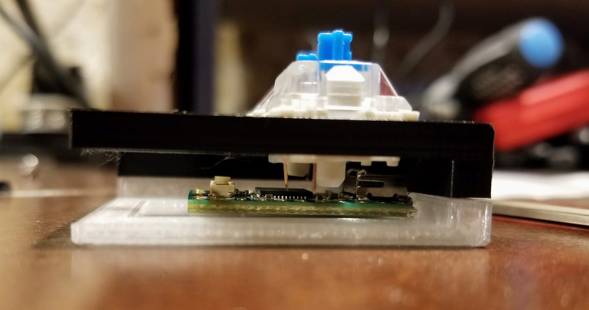
As my CAD model showed, the switches and the teensy just clear each other. Assuming there are no crazy wires, it’s perfect. It’s really hard to get a sense of size in a CAD model, so I’m very happy with how thin the whole base is when assembled. I’m also incredibly satisfied that my choice of 10 mm screws is just right: fully into the nut on the backside, and doesn’t stick out to scratch whatever the board is sitting on. I still plan to put rubber feet on the bottom anyway so it doesn’t lide around.
The opening for the Teensy board inside the bottom of the case was almost right. I stole all the dimensions for this from the SiCK-68 again. It’s mostly free in the case, but the end of the board is press fit into a horizontal slot in the back of the bottom piece. The slot means there’s an unsupported overhang to print. We tried printing with supports, but it’s such a tiny little piece that the support didn’t really exist, and the Teensy didn’t fit in. But a little work with a knife cleaned up the sagging overhang and we could cram the board in. It’s now protected from being pulled out if you yank on the USB cord, but there’s nothing to stop it from coming loose when you push it from the outside (like putting in a USB cord.) The easiest solution is probably just a dab of hot glue when everything is finally put together. No reason to overcomplicate this.
To keep the edges of the case from feeling to sharp, I also included a chamfer along the top and bottom. But as you might be able to tell from the picture above, it’s basically non-existant. (Again, really hard to judge scale of things in a CAD model on a screen.) So I’ll also bump up the chamfer size.
Lastly, I didn’t end up being happy with the clear PETG for the bottom of the case. Having it printed in a different color ends up emphasizing the fact that it’s all 3D printed. And the clear filament didn’t end up being super clear and looked a bit dirty. So I’ll just make both parts black PLA for a stealth look.
Production
In theory, the CR-10S has a large enough print bed to do both the top and bottom pieces at once (which Cura told us would take 29 hours to print, but only 157 g of filament). In practice, the print bed was slightly bowed and didn’t print well near the front and back edges; the extruder was too close to the bed. It’s possible to add a sensor to the printer to adjust for that, or to do a manual adjustment, but it’s not worth the time to try and figure that out when there’s a deadline at hand. Instead, we can just print one piece at a time.
First up: 15 hours to print the top plate.
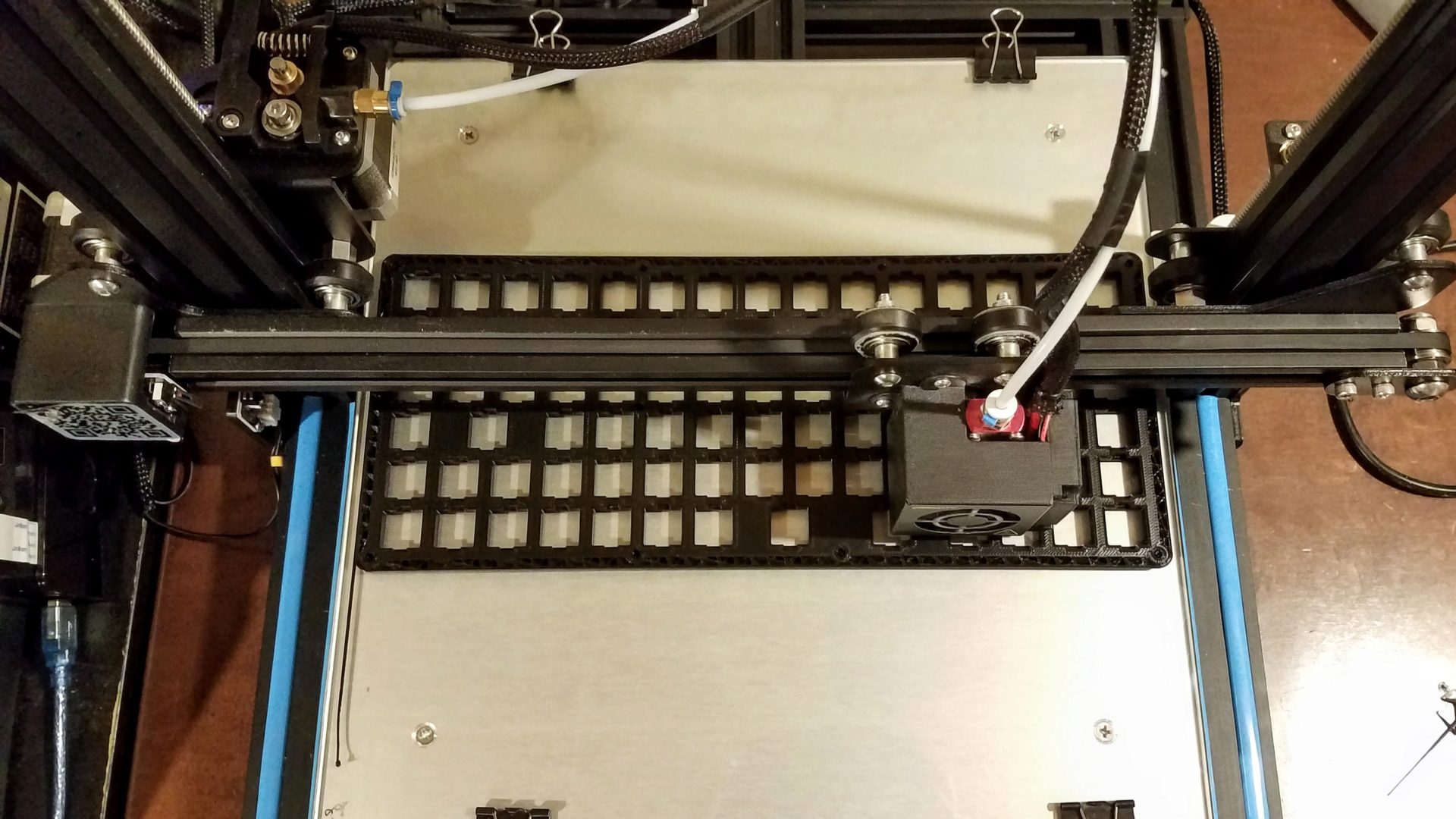
It looks kind of comical, when the printer can do up to 400 mm on the Z axis and I’m using 8.2 mm of that. But at least it seems to be sticking well to the bed.
And it’s finished!
One corner came up a tiny bit, but it’s just a little rounded and barely noticeable. Definitely not worth re-printing.
The bottom of the case is only a 10 hour print, but the first layer is 1:15 of that. The first 8 layers take a total of 8 hours, printing that huge base, but then the next 24 layers for the walls only take 2 hours! That giant first layer is also a real test of the levelness of your print bed.
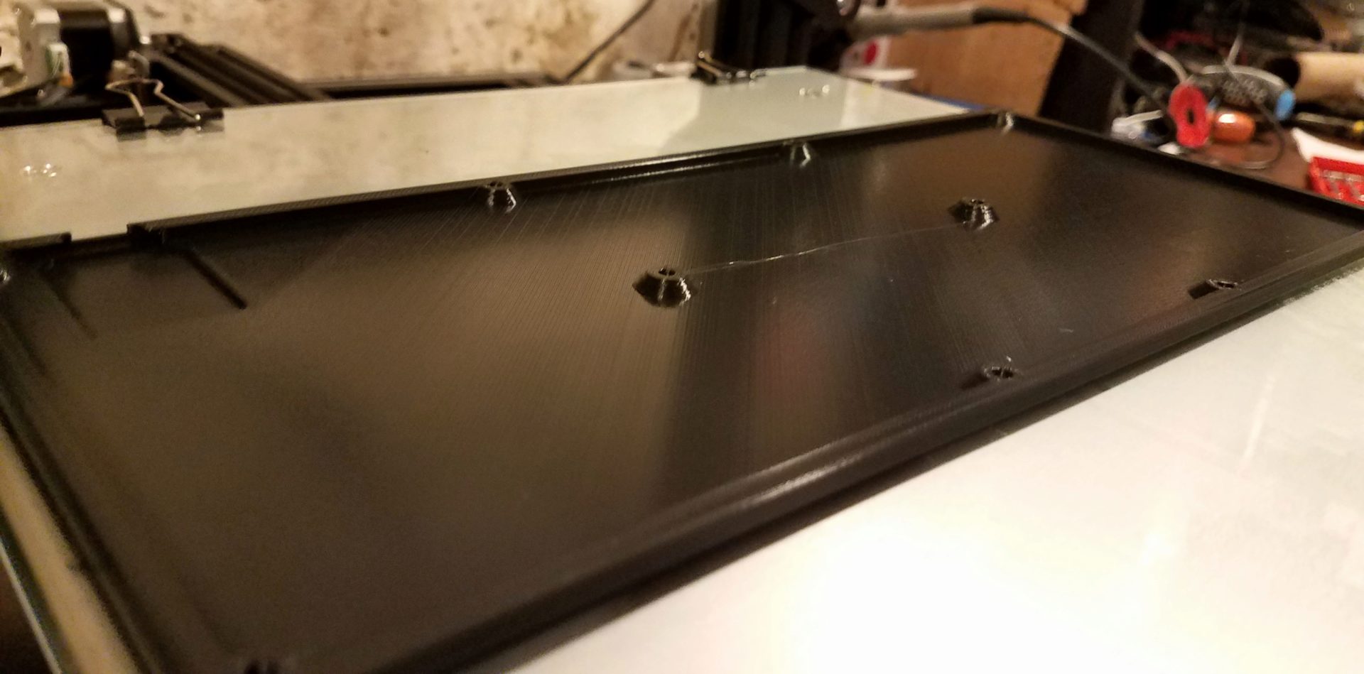
Check out that beautiful top finish, which no one will ever see because it’s inside the keyboard.
In a moment of truth when we got the pieces, from Clark, we tested the tolerances. Both pieces warped a little (the long way) from cooling, but that shouldn’t be an issue because it’ll all be screwed together. The switches have a tiny bit of wiggle to them. They’re definitely not coming out accidentally, though, and I’m guessing that little wiggle won’t be noticeable when the whole thing is assembled. (And if it is, a tiny drop of hot glue with fix it.) The screw heads fit nicely with their increased tolerance, and you can get all of the nuts in easily using the screw pulling technique that I learned when building my Prusa MK3S printer.
I screwed the whole thing together with all 10 M3 screws. One screw end sticks out a tiny bit and scratches the table This is where one corner of the top plate pulled off the bed a bit, so the screw head hole is deeper than it should be. I could add a bit of support inside the hole if I want to prevent this, but it won’t be a problem once I add rubber feet to the bottom.
When assembled, though, the whole thing is incredibly sturdy; there’s hardly any flex when trying to bend or twist the keyboard, or when pressing down on the top plate. (Thanks to the support screws in the middle, I think.) But there is a significant problem: when sitting it down on the table, it doesn’t lay flat. It sits on two diagonal corners and rocks back and forth across the other two. There are two ways I can think of to fix this. The lazy way would be shimming the rubber feet – adding a bit of thickness underneath one or more of the feet until it sits flat. But the more proper way would probably be with Clark’s suggestion to warm it up slightly (there’s a 60 deg C oven in his lab) and put a weight on it to force it flat. If we take that route, it needs to be done before we actually insert all the switches and start wiring it up.
Before we get to that (which will be after the final exam for this class, so I actually do some studying), some pictures to show off.
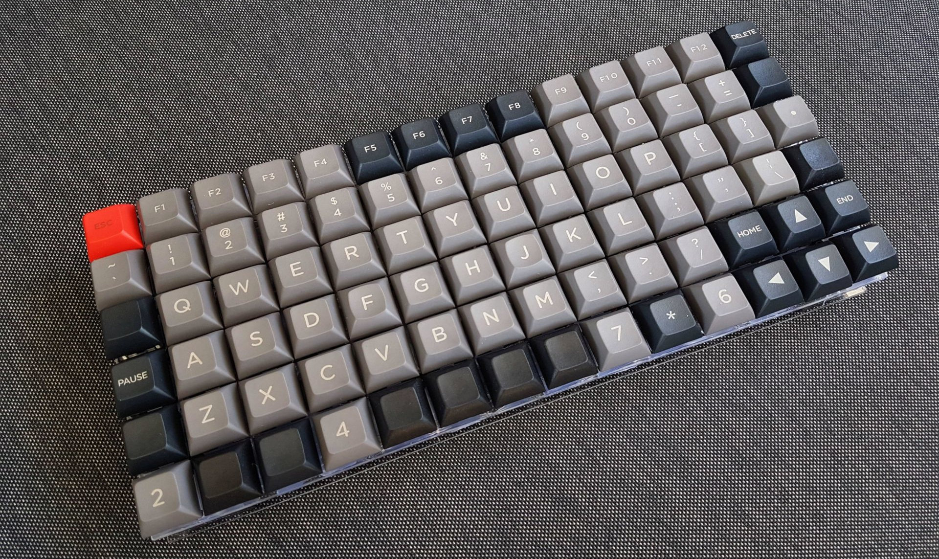
First, a size comparison to my other keyboards: ErgoDox Infinity and Magicforce 68:
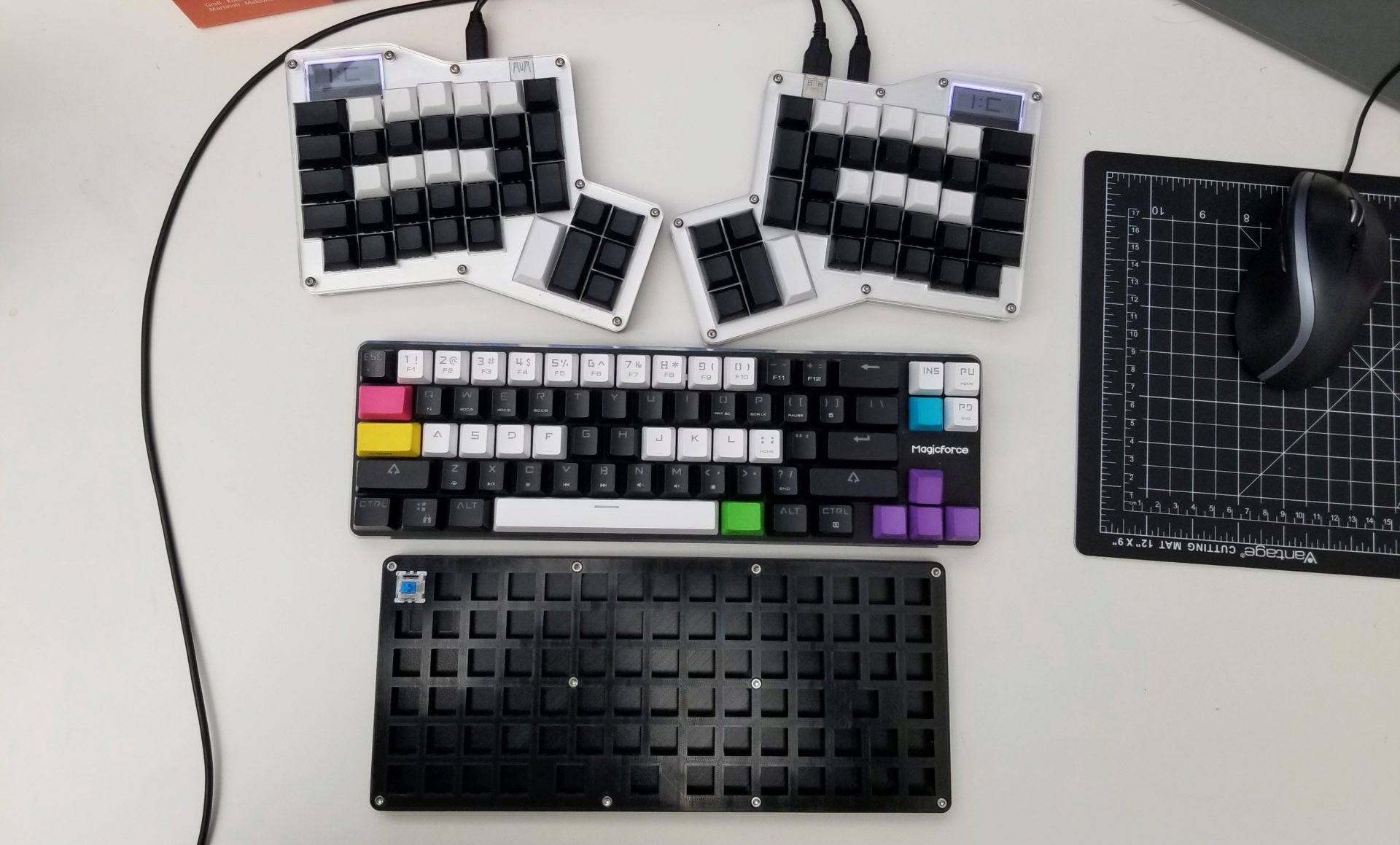
It’s narrower than the 68-key keyboard but deeper. (After all, it does have to squeeze in 19 more keys somewhere.) Overall, I’m pleased by the compact form factor I’ve managed to squeeze this into. It’s also a very thin keyboard:
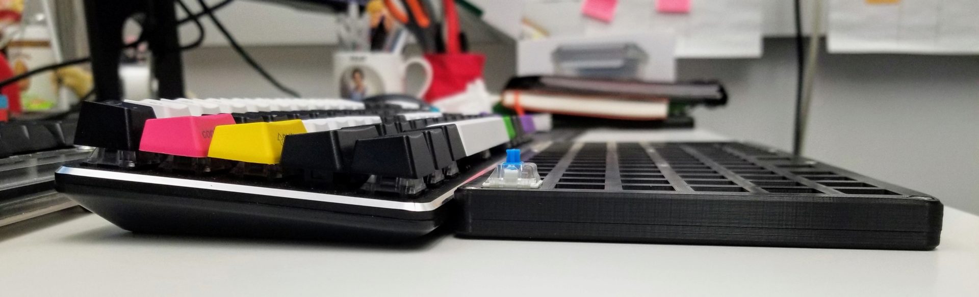
It’s slightly thinner than the thinnest part of the Magicforce keyboard (without rubber feet, though). I’m excited to start turning this into something functional.
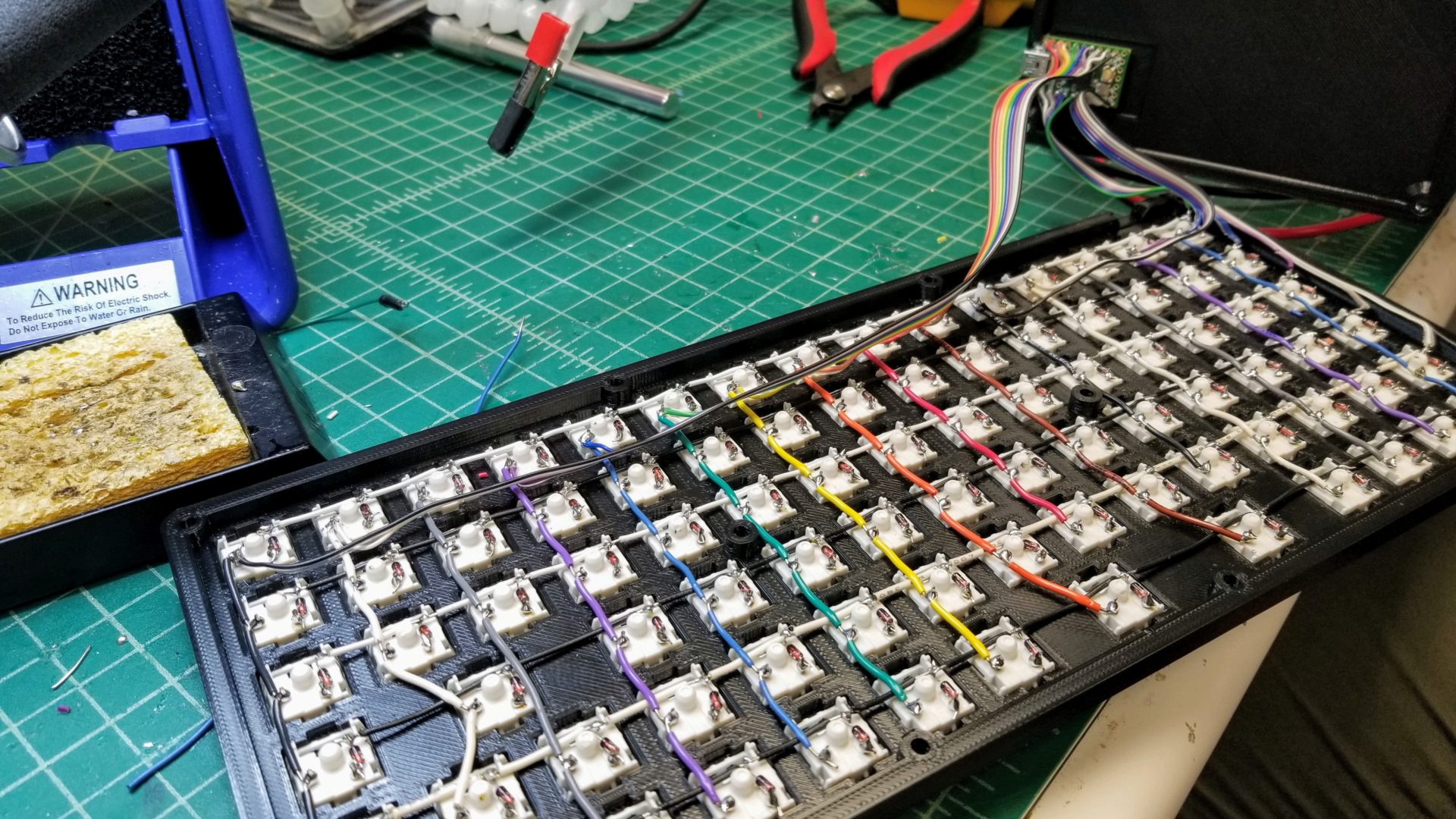
Assembly
Wiring the rows
With the final exam finished, there’s now time to put this whole contraption together!
Popping all 87 switches into place on the board was so satisfying.
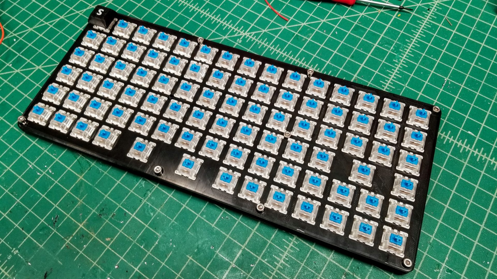
- Shaping/cutting the diodes, soldering them on
- Cutting wire for rows (gaps, stripping)
- Soldering rows, cleaning up wires
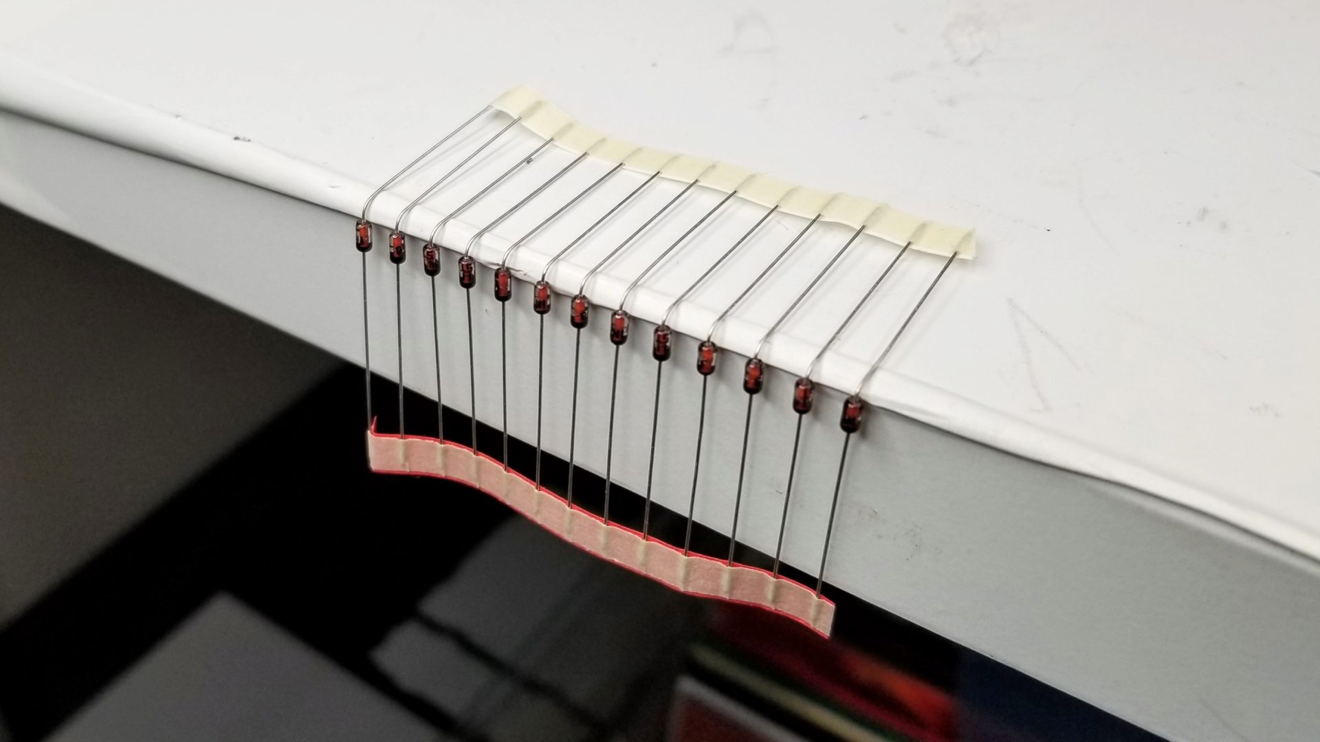
Next, we had to shape and cut all 87 diodes for the keys. Because the switches just have pins sticking out, you want to make your life as easy as possible when it comes to soldering them on. That means creating a little loop on each diode to stick over the pin, then solder that without it falling off when one hand is full of solder and the other has the soldering iron. (Soldering is the primary situation in which I want a robotics third hand.)
So first we bent all the diodes into an L shape. This provides sort of a nucleation point for the loop you make next. It’s important to do this on the correct end of the diodes. Because we want to allow current to flow into the wires for the rows (from the columns), we need to attach the anode to the switch and the cathode (the end with the black line) to the row wire. So we’re making loops on the anode (non-black-line) end.
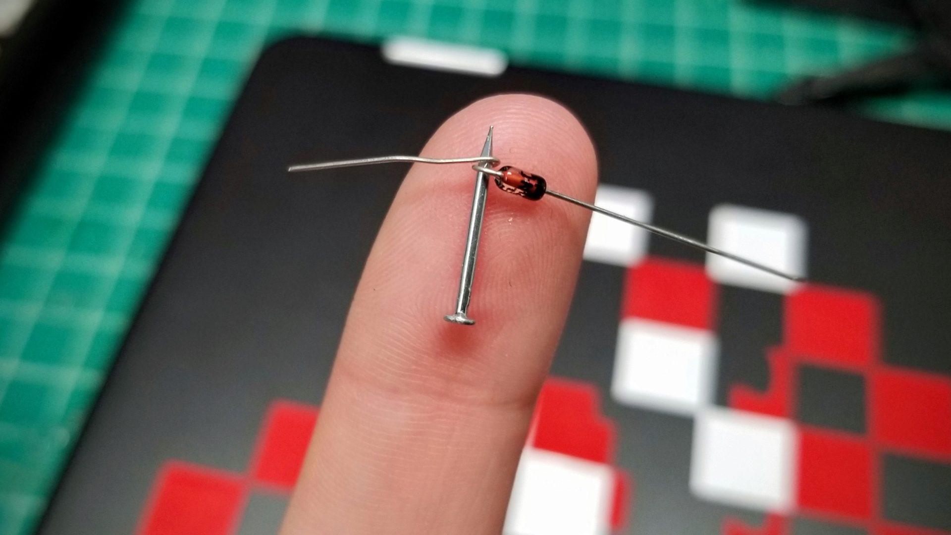
Then, to make the loop, we had to wrap the lead of each diode around something slightly larger than the pins on the switches. The best thing we could find in the lab was… a small nail. It looks incredibly sketchy, but it did the job.
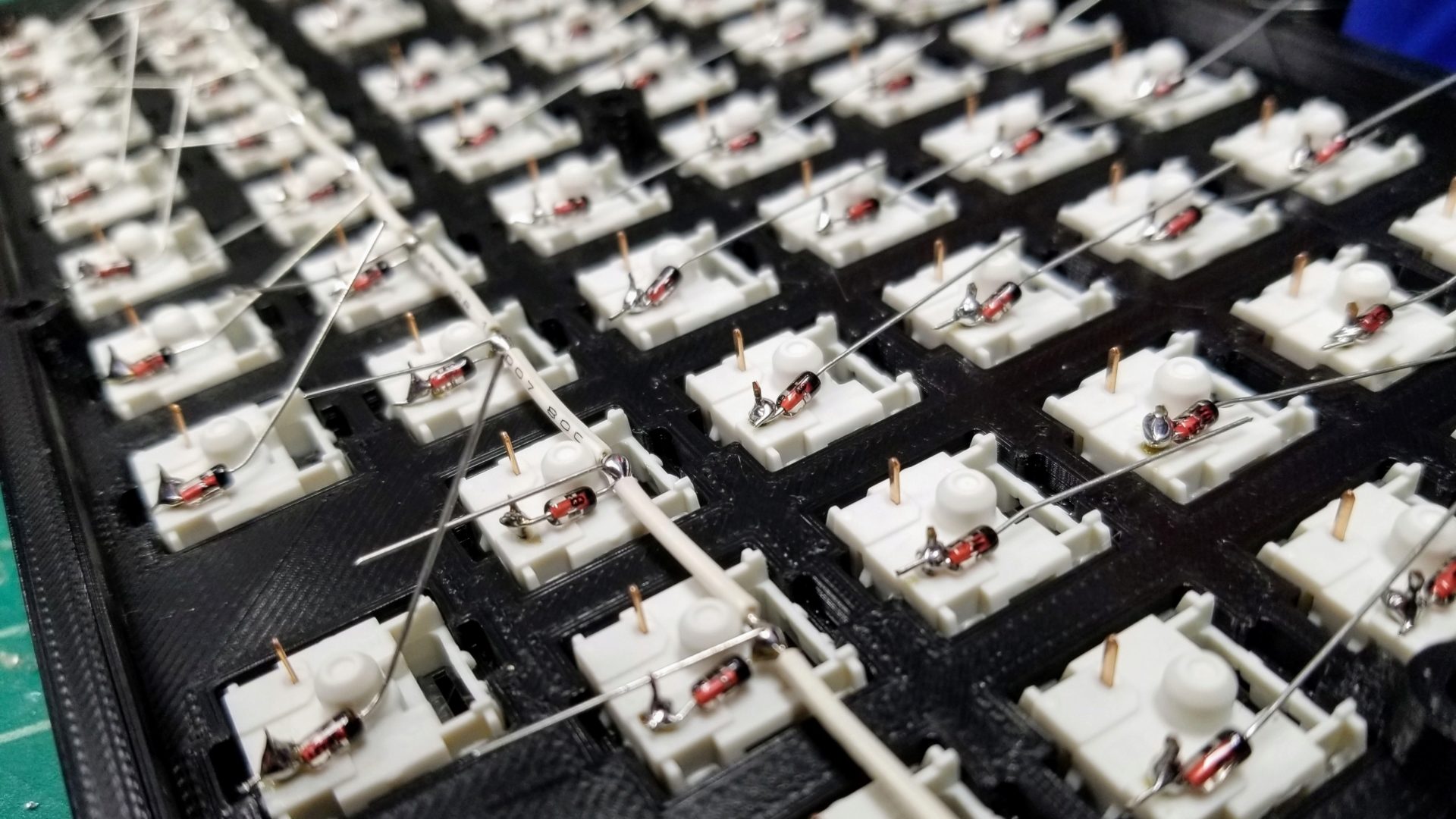
You can then trim the ends of loops on each diode and solder them all onto the switches. For soldering, each of the diodes has its long cathode end pointing up (so we can attach it to the row wires). That means its easiest to start by soldering the diodes in the top row, so you don’t have to worry about the leads of the other rows’ diodes getting in the way.
Turns out 87 diodes is a lot, so we took turns on this part.
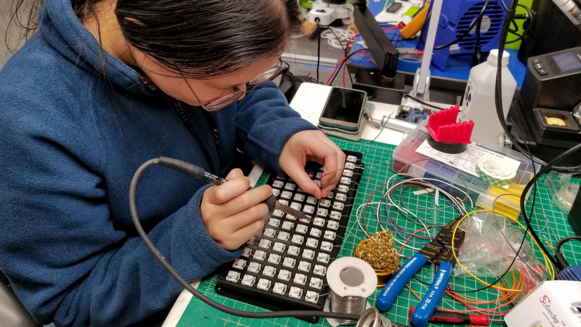
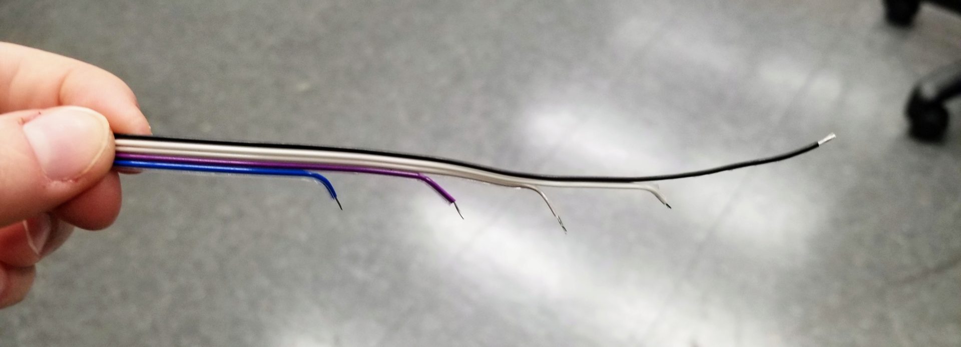
Next, we have to wires each of these diodes together into a row. To make it harder to short the row wires and column wires of the matrix, we want to keep the wires between each of the switches insulated. That means a lot of wire stripping. To make our lives easier, we employed some math to strip our wires beforehand.
Switches are spaced at 19 mm apart, and we want to leave ourselves a little gap in the insulation to actually solder the diodes to the wires (say, 3 mm). For our 15 switches in a row, that means we want 14 sections of insulation, each 16 mm long. To make sure we had enough wire length, we first stripped about 5 cm of insulation off the end of our solid core wire. Then we marked out our 16 mm sections with Sharpie and cut with wire strippers. Now we can slide the little sections of insulation around as we solder to put them in between the switches. It turns out its not worth trying to line up all the little gaps before you solder; just do it for the next switch as you go.
To make it easier to solder, we again make little loops (well, half loops this time). Lay the wire down just north of the bump in the middle of the switch, with the diode cathode leads underneath. Then fold the first diode up and over the stripped section of wire (forming a little U), and solder. Then you can slide the next section of insulation down tight to this (preferably after you let it cool) and move on to the next switch.
The one challenge we encountered with our nice 16 mm insulation sections is that it doesn’t apply when you have switches more the one switch-length apart, like for the enter key and the space/backspace keys on the bottom row. But it turns out the math here isn’t complicated. The enter key is spaced in between two columns, so it’s 1.5 switch-lengths away from the next switch in the row (about 29 mm). Subtract our 3 mm stripped section, and we need a 26 mm insulation section instead of 16 mm: \(1.5 \times (19~\text{mm}) - 3~\text{mm} = 26~\text{mm}\).
We can also do the same thing for the gap between the 2u keys in the bottom row: \(2 \times (19~\text{mm}) - 3~\text{mm} = 35~\text{mm}\).
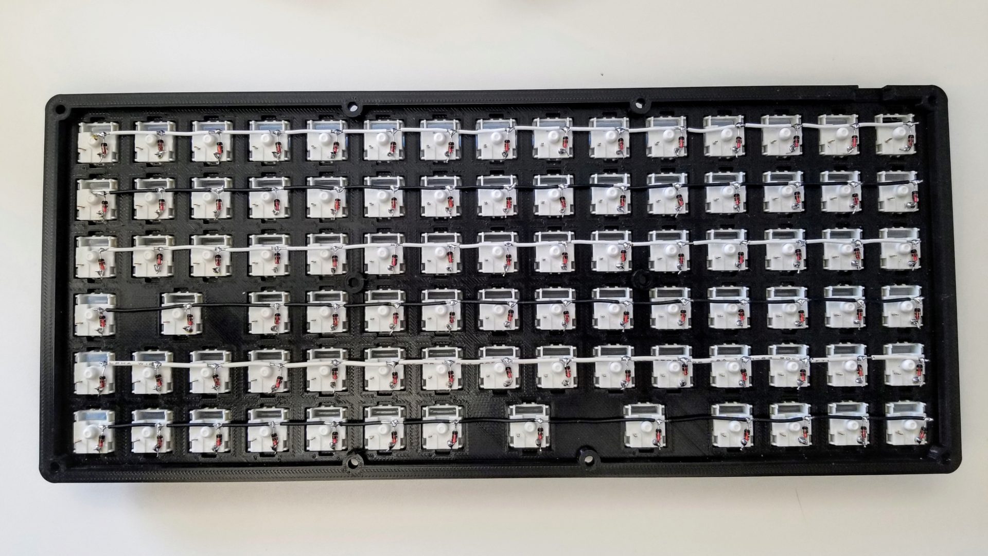
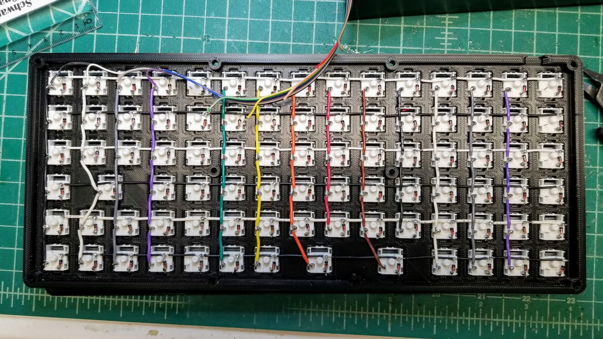
We took turns stripping wire and soldering, then trimmed up all the loose wire and and ends of the diode leads.
Wiring the columns
This is very similar to wiring the rows, but this time there are no diodes to connect to; we’re soldering all of the column pins together directly. This does mean that we don’t have any convenient little loops anymore, but we can make loops in the wire as we go to make soldering easier.
Stripping the wire is also pretty much the same as for the rows, with 19 mm vertical spacing for the switches as well. The one trick here is that some rows only have 5 rows of keys, while others have keys in the column slightly offset from the others. (See the wiring diagram above or the result picture below.) I could calculate the angle between the keys again for this, but it’s really not a precise operation, so I just approximated the distance between the pins with a ruler and subtracted 3 mm.
Here, each column is slightly different, so it was useful to keep them all in order to prevent confusion. (The color coding here is also useful. But we forgot to grab blue wire, so we’ll have to come back to those columns.) Because we also have to wrap the wires around each of the pins, we started with a longer stripped length at the end of the wire so we wouldn’t run out.
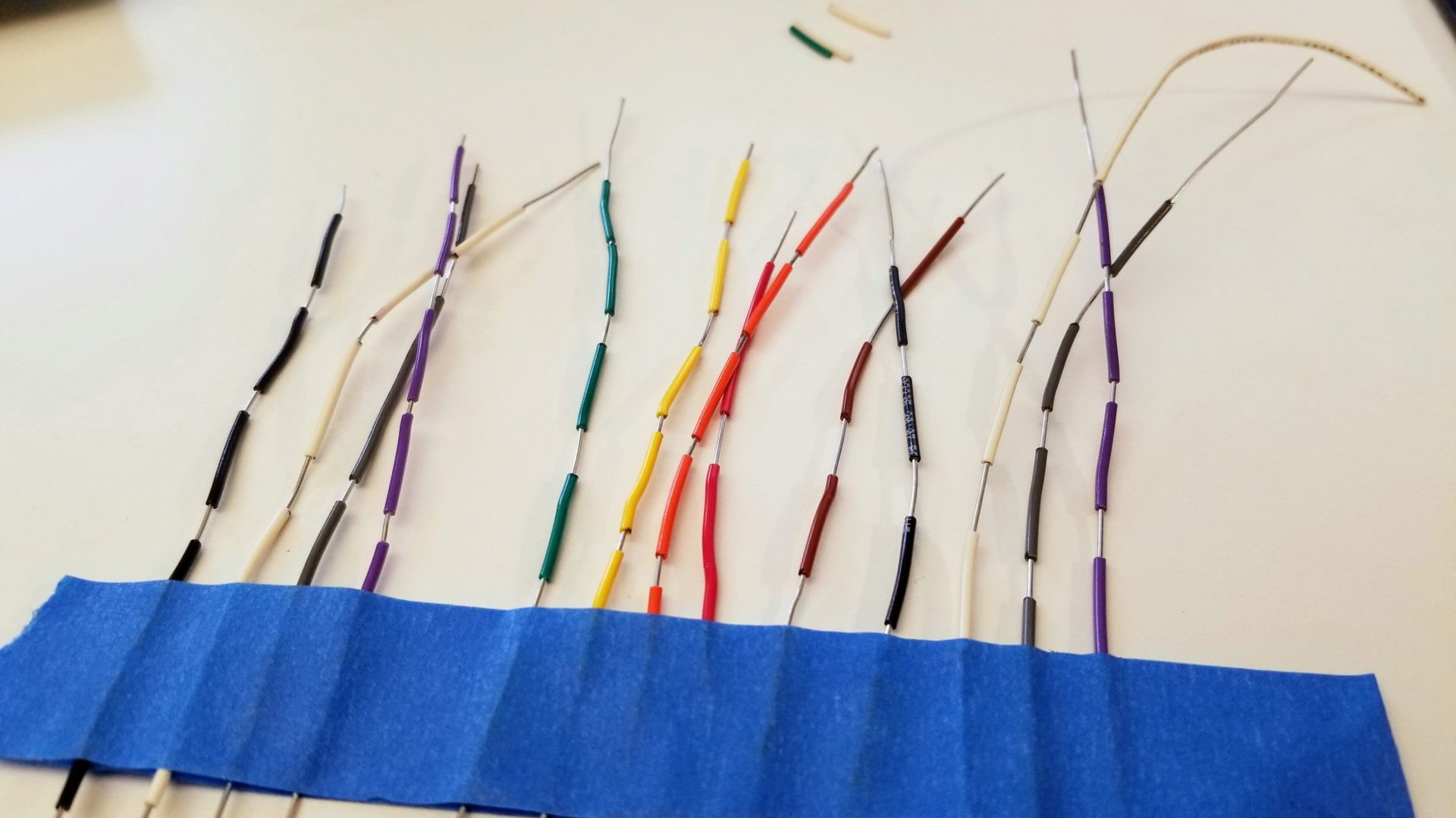
(Update: the first one wasn’t long enough and I did run out of wire…)
The first loop was easiest to make using a small pair of pliers, but after that it wasn’t too hard to use the pin on the switch to wrap the wire around. (Just don’t use too much force, or you risk breaking off the pin.)
Then rinse and repeat. Like the rows, it’s pretty tedious, but at least there are fun colors this time.
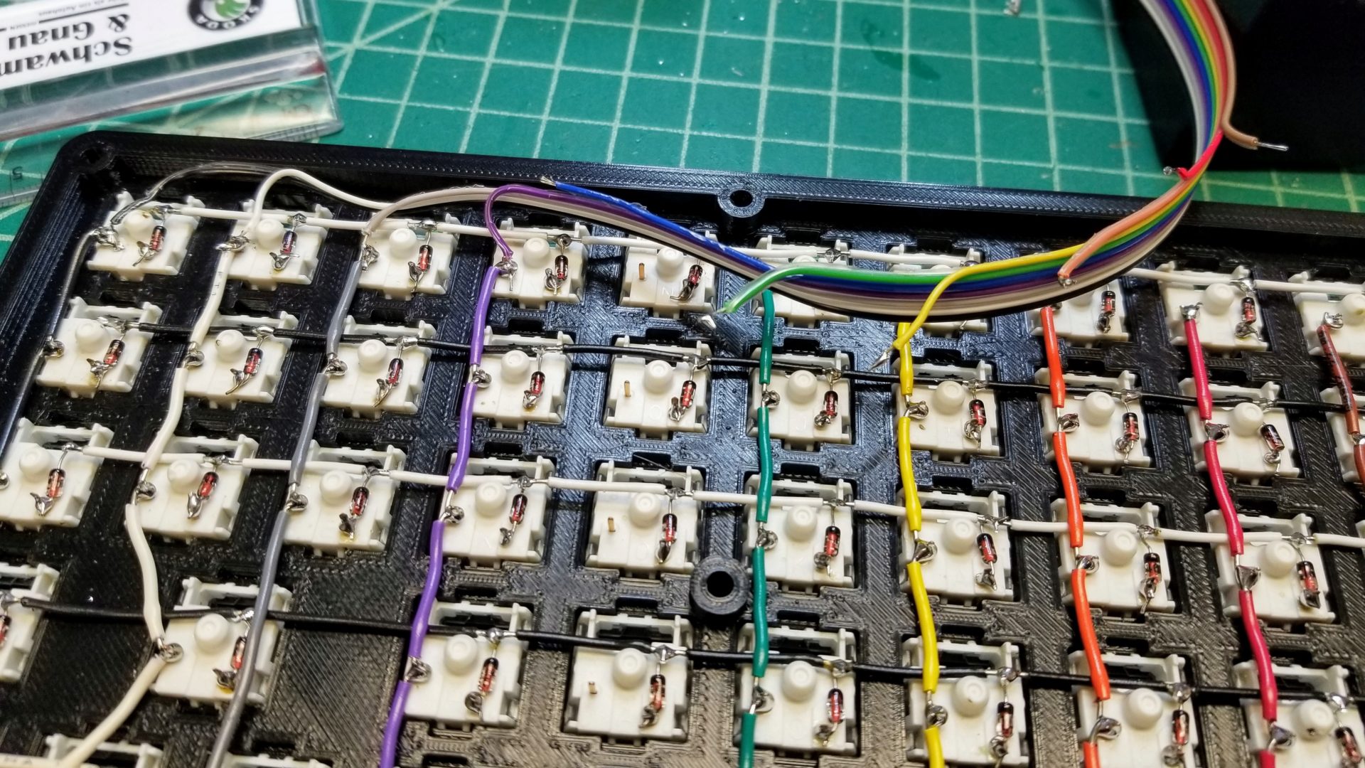
Wiring the microcontroller
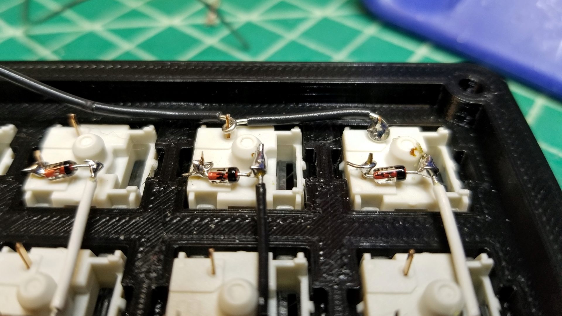
With all the columns wired (except for where we were still waiting on blue wire), we now have to connect the whole keyboard matrix up to the Teensy 2.0 microcontroller. As planned, the column colors matched the color order on ribbon cable, which will let us make the wiring more compact. With the keys spaced about 2 cm apart, we trimmed each successive wire on the ribbon cable 2 cm shorter than the previous one to avoid excess wire everywhere.
It doesn’t matter where on the row or column wire you actually solder to, since it’s a single line. But for making it look tidy, we stuck to wiring on the top of the columns and one side of the rows.
Then we needed to solder the other ends of the ribbon cable into the pins on the Teensy. We did plan enough ahead to make the pins go in order, but it’s still tricky to solder tiny stranded wire into tiny holes.
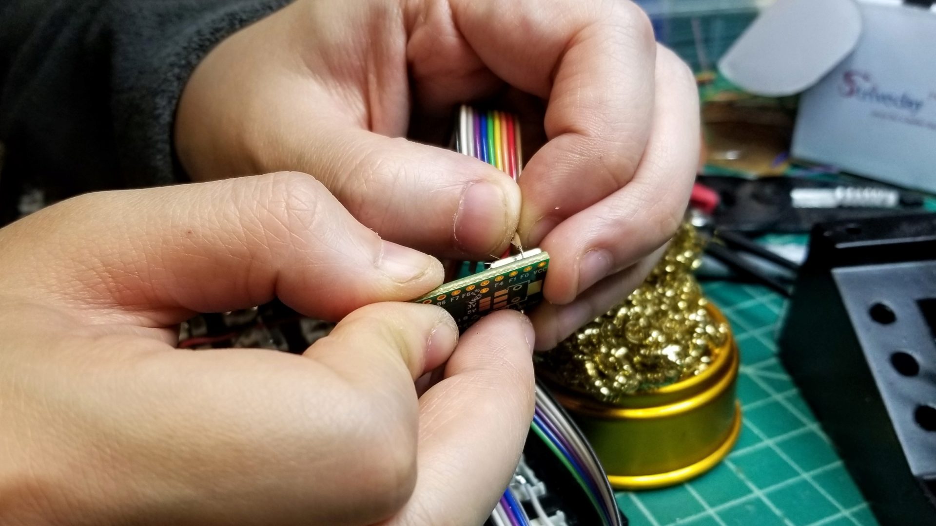
We did a quick continuity test with a multi-meter to make sure nothing was shorting between pins (in case a single strand of wire went astray). With no errant beeping, we were ready to stick the Teensy into its press fit slot in the bottom of the case and close up. The closing part was a little trickier than anticipated. Since we were afraid of making the ribbon cable too short, we instead ended up with a lot more excess ribbon cable than planned, which was difficult to squeeze in. Just don’t look too closely at the back of the case to see where it doesn’t quite close flush with all the screws in place. (But at least all that wire helps prevent USB port from slipping when you attach a cord, and it seems to have solved the problem of the case not sitting flat.)
Then we just pop on the keycaps, and we have a keyboard!
(Alright, that’s a little out of order. We had the sense not to close up the keyboard until we programmed it and knew that it all worked.)
Programming
We’d already done a lot of the legwork on the firmware beforehand (setting up the layout and getting something that compiled), so that put us in good shape to try programming the board as soon as we had it wired up.
The Teensy comes with its own Teensy Loader for programming the board, which is just a nice GUI interface for AVR programming. In theory, this is simple: press the reset button on the board to put it into bootloader mode, then the GUI will let you hit “Program” and it will upload the compiled hex file to the board over the USB cable.
In practice, that didn’t work. You press the reset button and the LED turns off like its supposed to, but the loader doesn’t seem to detect the change.
First thought: maybe the computer isn’t detecting the connected Teensy. Plugging it in didn’t make a new device show up under /dev/tty*. But a quick Google search showed that it won’t turn up there until the board is programmed. And running lsusb did show Van Ooijen Technische Informatica Teensy Halfkay Bootloader. So the computer is detecting it.
We were at a bit of a loss until I remembered a similar struggle from the very first year of my PhD, when the KiloGUI didn’t want to let me use the controller to program the robots; it detected the USB device, but it wouldn’t let me send a hex file to it. The problem turned out to be a permissions issue: somehow, my user wasn’t allowed to write to the device. The hackiest solution back then (and still now, because I’ve been too lazy to figure out and solve the underlying issue) was to just run it as root. So we launch the Teensy loader from the terminal with root, and it worked!
Well, it programmed, at least.
We tried to type on it, and it did successfully produce letters as we expected, but not the correct letters. The top row (function keys) seemed to mostly be OK. But then after that, the letters all seemed to be shifted to the right by one key (e.g., you try to type W and get Q instead). But at the very end of the board, the arrow keys seemed to be working. Our first thought was that one of the columns wasn’t wired up correctly, but the fact that not everything was off by one column suggested that it wasn’t a wiring issue or an incorrect pin specification.
So we went back and looked at the keymap specification in our firmware. It turned out I had accidentally put in “F6” twice, so everything after that (the keymap is specified as a single flat array), was shifted by one. But then the code should have failed to compile, claiming that the keymap had 88 keys instead of 87. So we had to go through the whole array key by key until we realized that the Caps Lock key was missing toward the end of the keymap, which also explained why the keys at the end of the board behaved correctly.
But now, it works! And I’m typing this on our newly functional keyboard.
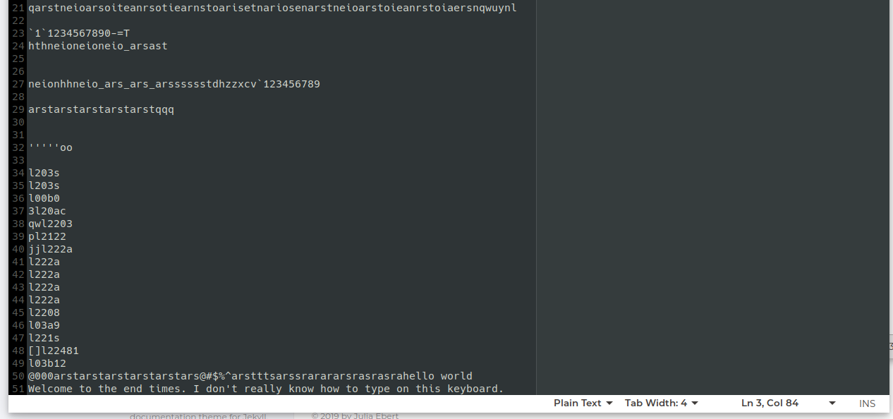
Look at the beautiful gibberish we can generate.
The last piece was the unicode. And we still don’t have that working. This was hacky to begin with, thanks to the HID specification only allowing keyboard key input (resulting in the OS-specific unicode input methods being simulated in the firmware and sent as a series of keystrokes). In Linux, unicode input is done as Ctrl+Shift+u, followed by the unicode string (such as 00bd for the fraction symbol ½), then Enter. And if you type that series of characters on the keyboard, it does create the unicode character. But the macro that’s supposed to do that on the keyboard just spits the characters 00bd instead. (You can see that in the picture above as well.) But we haven’t had the time to get back to that to debug it further.
For now, though, we do have a fully functional keyboard! It just doesn’t (yet) have the power to type emoji.
January Update
I did finally get the unicode to work, with a caveat (for now). The problem was that I had the base layer in the firmware set to QWERTY, and then had my computer switching the layout to Colemak in software, like I’ve always done. The problem is that this also translated the character strings that the keyboard was trying to send to generate unicode. I was trying to get it to send Ctrl+Shift+u, but the computer thought that that was a u from a QWERTY-programmed keyboard that had to be “translated” to Colemak, so it interpretted the series of keystrokes as Ctrl+Shift+i instead… which does not give me unicode. Instead it just followed this by spitting out the series of characters that should have made up the unicode.
But that spitting out the characters was actually the clue that let me solve the problem. For example, instead of typing out 1F620 to give me an angry face emoji like I expected, I got 1T620. Guess what? Typing f on a QWERTY keyboard gets translated to having typed t on a Colemak layout.
The way I truly figured this out, though, was by posing the question on a forum, trying to write up a thorough question, and then figuring out the solution to my problem in the process. I rubber duck debugged myself.(I left the question as a monument to my ability to sort of solve my own problems, and also in the hopes that it might help someone else in the future.)
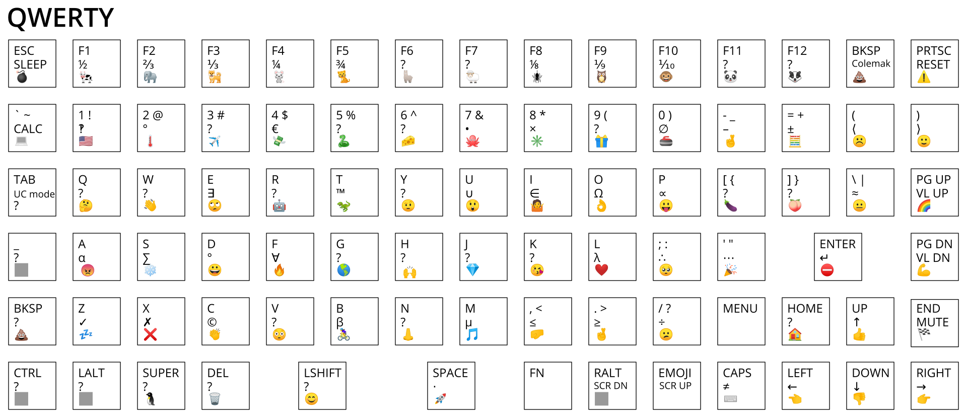
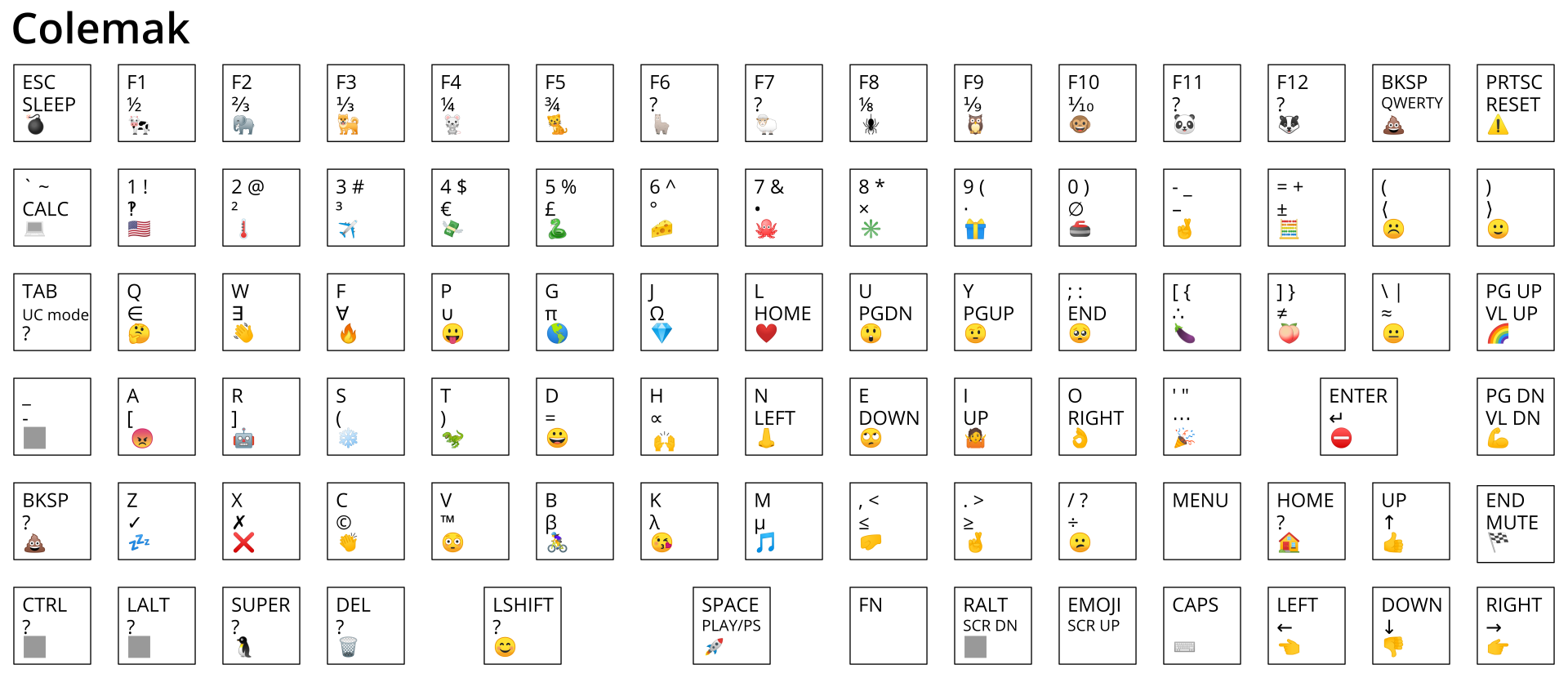
The solution was to change the base layer in the firmware to have a Colemak layout instead of QWERTY, and then have the OS treat it as a QWERTY keyboard. Essentially, changing where the burden of layouts is. (Side note: in order to still retain use of the dead keys to get things like umlauts, I had to use the “English (intl., with AltGr dead keys)” layout in Ubuntu. Maybe I should add those to the Function layer.)
The caveat that I mentioned, though, is that you can now only type with a Colemak layout at the moment, because I haven’t gotten around to having the option to switch the layout on the keyboard to QWERTY. It’s totally possible, but it’s late and I’m tired right now. The additional challenge with this is that I want to have the unicode keys line up in a somewhat meaningful way with the letter key they’re on top of, which I think requires having multiple function/emoji layers to handle this. I’ll try it… later.
Since creating this new on-keyboard layout, I quickly realized a major issue: my keyboard shortcuts aren’t working in some programs. In some programs they work fine, like Chrome. But in VS Code, I realized that although I could type the letter f, typing Ctrl+f wasn’t opening “Find”. The VS Code wiki on keybinding issues provided a solution: in the settings, set "keyboard.dispatch": "keyCode". Don’t understand why I had an issue or how this solved it, but it works… for this program. But I’ve also noticed the same issue in Inkscape, which I completely can’t use without keyboard shortcuts.
How does this work?
A keyboard matrix is pretty simple to set up and wire, but it’s not necessarily intuitive how it’s possible to figure out the key pressed from this wiring setup – and that’s the interesting part of this project! I found these explanations from komar’s techblog and PCB Heaven useful.
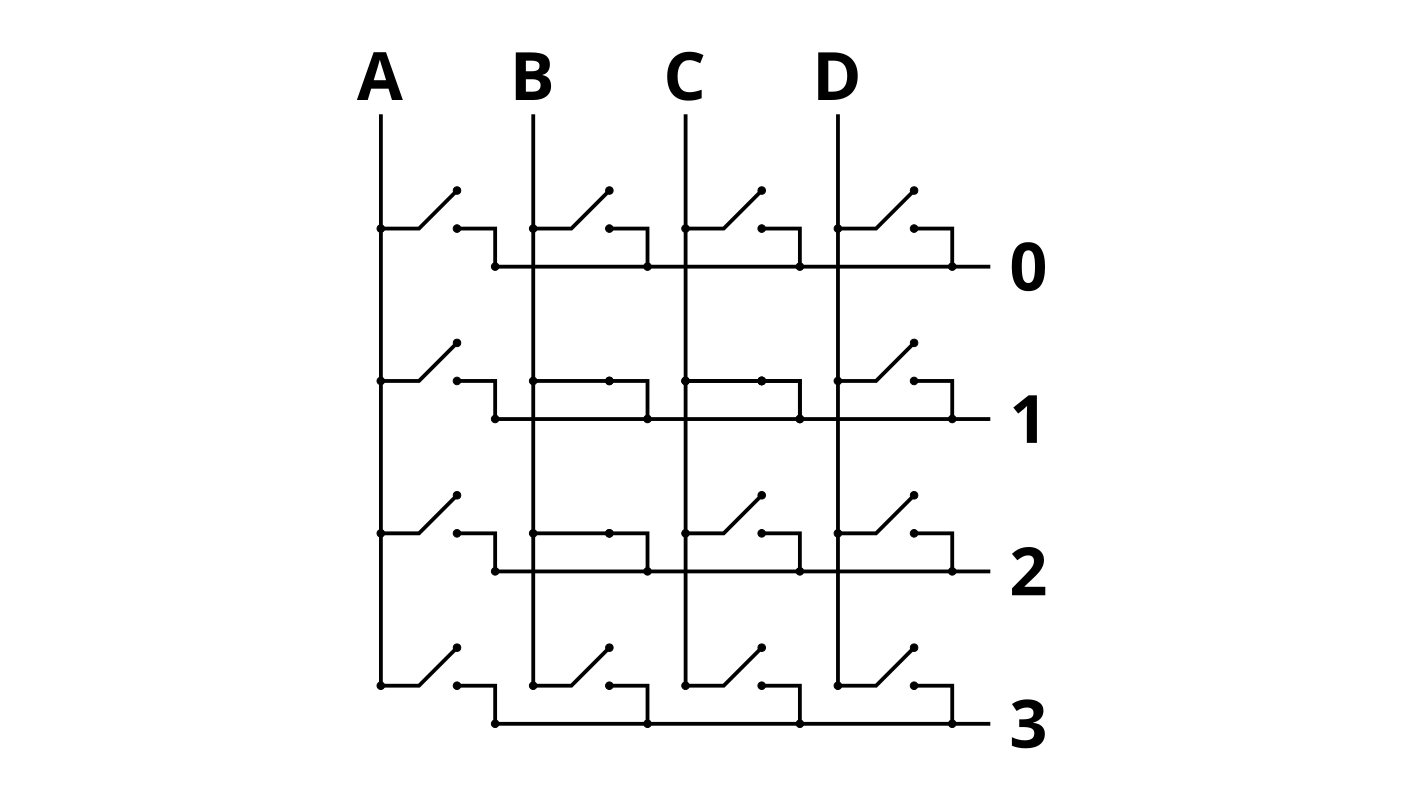
Let’s start with a simpler version of what we actually wired by removing the diodes from the equation. Each key is still a switch connecting a column wire and a row wire, but for now let’s say we didn’t put a diode in between the switch and the row wire.
The first thing to understand is that the rows and columns have different roles in the process. The columns are “out” pins on the microcontroller, and the rows are “in” pins. In the most basic sense, the microcontroller sets a digital voltage low (0 V) on the pin for a particular column, and then checks if that flows through to end up with the same voltage on the “in” pin for each row. If you press the keyboard key, it closes the switch between the row and the column, and you’ll see the column output on the row input. When the switch is open (the key isn’t pressed), the voltage for that row will be high because the microcontroller has an internal pull-up resistor.
For example, if you pressed the key in column B, row 1, the MCU would see a signal on the row 1 input pin only when it sets column B low.
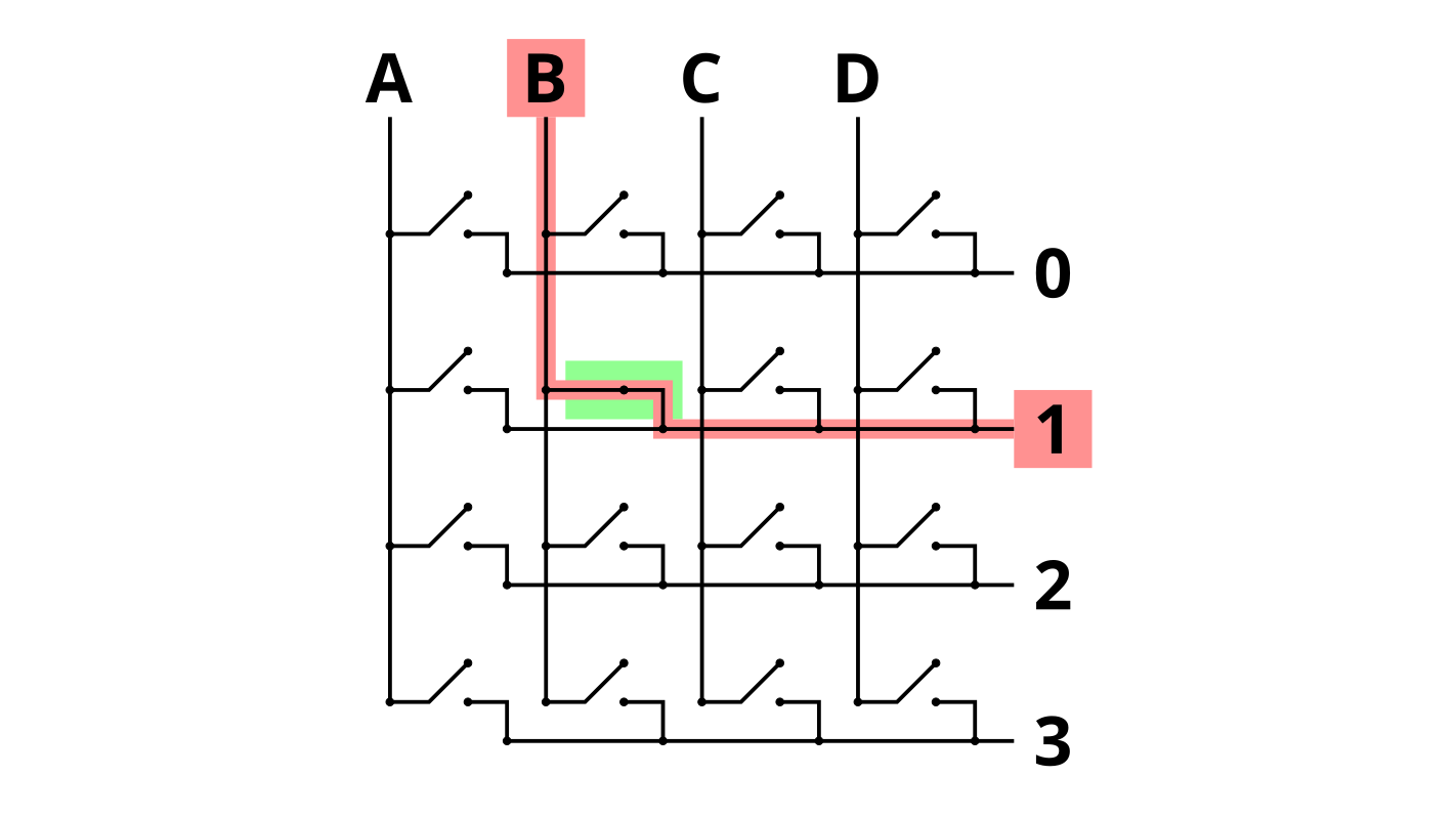
If you press multiple keys in the same column, you’ll see multiple row input pins go low:
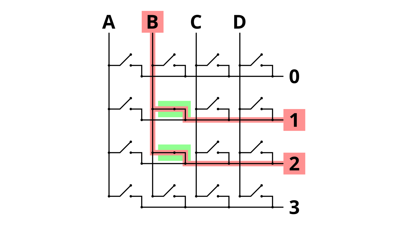
That approach works if you’re just looking at one column. If you set the voltage on multiple columns at once, you wouldn’t be able to tell which column was causing the signal to go high for a particular row. So you just set and check one column at a time, but you cycle through them. Because you’re doing this with a microcontroller, you can do this really fast, cycling through at multiple megahertz speed. This is so much faster than the speed at which a human can type that we can get away with this just fine.
So far, though, we’ve hidden a tricky part from you. If we just had this set up with no diodes, we can run into a tricky situation if we press the right combination of keys. Because at this point, we just have wires that can be connected or not connected; there’s nothing that’s special about something being a row wire or column wire.
Now, let’s imagine you press 3 keys, as shown below:
When the microcontroller strobes the B column, it looks as expected: inputs for rows 1 and 2 are active:
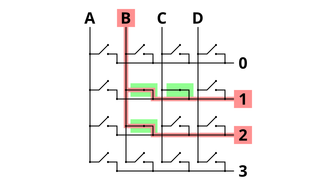
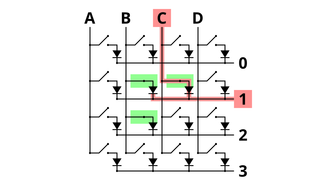
But something funny happens when column C is active.
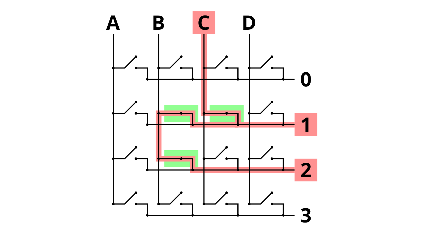
Rows 1 and 2 both show up as active again, even though we aren’t pressing the key in column C, row 2 isn’t pressed. But because the switches in column B are still closed, they are connecting rows 1 and 2. This is called ghosting: key C2 shows up as a keypress, even though the key isn’t actually pressed.
This can also cause a problem called masking or jamming: if you now pressed key C2, the key press would be masked (not detected), because the microcontroller already believes that it’s been pressed.
How can we fix this problem? This is where the diodes come in, inserted between the switch and the row wire.
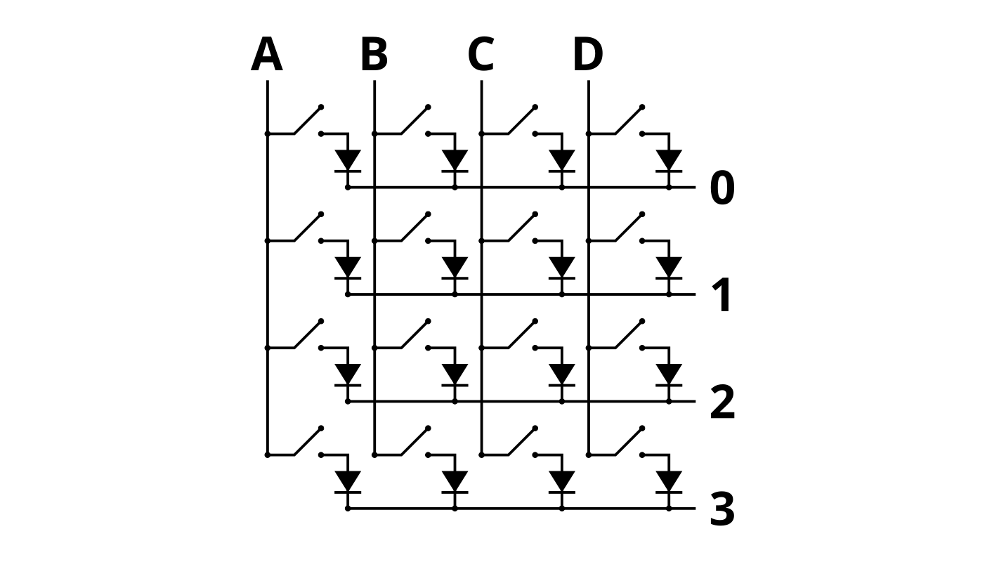
In the non-tricky (non-ghosted/masked/jammed) situations we saw above, the keyboard behavior will be exactly the same; the diode will not prevent the signal from dropping to ground between the column and the row.
But its benefit becomes clear in the ghosting situation we saw before:
The 0 V can’t go “backwards” through the diode connected to the switch in colmumn B, row 1. The diodes allow you to decouple the keys by preventing these errant paths.
Now we have a functional keyboard without ghosting!
Bill of materials
I’ll update this as I go. You can get this stuff cheaper on eBay/AliExpress, but I have a deadline, so they’re from Amazon.
| Item | Quantity | Unit Price | Total |
|---|---|---|---|
| 1N148 diodes (pack of 100) | 1 | $4.99 | $4.99 |
| Teensy 2.0 microcontroller | 1 | $19.20 | $19.20 |
| Gateron Mechanical switches (pack of 90) | 1 | $34.99 | $34.99 |
| Hatchbox PLA filament | |||
| Rubber feet (pack of at least 8) | 1 | $2.48 | $2.48 |
| M3x10 mm screws and nuts | 10 | ||
| Solid-core wire | |||
| Solder | |||
| TOTAL: | $59.18 |
Non-consumable equipment:
- 3D printer
- Wire strippers
- Soldering iron
TODO
- Fix the QWERTY/Colemak issue (see here)
- Make QWERTY layer accessible by toggle (perhaps
Fn+upper delete key) (see info here) - Make unicode (emoji and function layer) align with the right letter layouts
- Maybe add umlauts/other stuff to reduce dependence on AltGr dead key layouts
- Or replace the right alt key (while in Colemak) with one that gives the dead keys for Colemak
- Make QWERTY layer accessible by toggle (perhaps
- Make a macro that outputs some stupid copypasta (because we can)
- Re-enable
UC_MODso it’s possible to switch unicode input modes (in case there’s a weird world where I’m not using Linux)