Quarantine Bot In Progress
Posted: 2020 March 29
Last updated: 2020 April 18
About
Are you stuck self-quarantining with a basement full of 3D printers and miscellaneous electronics?
No?
Well, Clark and I are. So we decided to use our free time, basement junkyard, and combined engineering powers to build a robot that could be sort of useful in this pandemic.
Here’s what we have in mind: a small wheeled robot with an arm on top that can grab things. In theory, this could be used to grab deliveries off of your porch so you don’t have to go outside. In practice, it will probably wander around and bump into walls, like a Roomba without the usefulness of being a vacuum cleaner.
As a mechanical engineer, Clark is excited about designing and building the arm and gripper. I’m excited about the possibilities of what we could program this thing to do, like using an Intel Realsense to detect and pick up particular objects. We’re both excited about over-engineering and over-designing this thing, and putting LEDs in it. Plus, I’m looking forward to seeing how a real engineer goes about designing and building something like this.
Initial Design Ideas
We’re trying to do as much of this as possible with the parts we have on hand. (Let’s try to reduce to the risk to Amazon warehouse workers!) From our initial scratch-paper design, here’s what we have in mind:
- All of the structural parts will be 3D printed. We’ll probably go with PETG over PLA because it’s less brittle. This includes the body, arm, wheels, and pulleys. For things like timing belts and tires, we can print in Ninjaflex TPU. (McMaster even provides CAD files for timing belts, which makes things even easier.)
- Because we also like things to look nice, we’re thinking about how to give this thing a nice aesthetic. We’re aiming for a sleek futuristic look with white and blue plastic, like a cross between R2-D2 and those stock photos of white plastic humanoid robots (but less creepy).
- Arm
- 2 links with a pincher gripper at the end
- 3 DOF powered by NEMA 17 stepper motors: bending at the base, elbow, and wrist. They’re controlled by linkages, and motors are inside the body, connected by timing belts/pulleys. We’ll rely on turning the body to get alignment.
- Gripper pinching controlled by a servo motor mounted on the arm. And we could even add some Ninjaflex gripper pads
- Body
- We’re thinking a tear-drop shape, wider in the back for all the motors, and narrower in the front. The nose has to be wide enough to fit the RealSense (plus the USB-C cable that annoyingly sticks out sideways).
- Since the arm will likely be reaching forward, placing it in the back of the robot will keep it from tipping the robot over if it grabs something heavy. The compromise is that this limits the workspace of the arm, since it has to reach over the front of the robot to get to things.
- We’ll put a strip of RGB LEDs around the whole body, because we can. Maybe they’ll be useful for debugging, but mostly they’ll be there to look cool.
- Drive control
- Differential drive, powered by 2 NEMA 14 pancake motors. We’ll align the base of the arm between the wheels, so we can just rotate the robot to control the rotation of the arm.
- Wheels will be 3D printed in PETG with Ninjaflex tires.
- We’ll use a caster wheel in the front for balance.
- Control & sensing
- Clark has a couple of Intel RealSense D435 depth cameras, so we can put one in the front of the robot for all of our sensing needs
- The brains will be a Raspberry Pi 4, which has USB 3 to work with the RealSense and should have enough computational horsepower for everything we plan on doing.
- For low level motor control/motor drivers, Clark has a spare RAMPS 1.4 board from a 3D printer. It can handle 5 motors, which will cover the 3 arm and 2 drive stepper motors.
- Someone made the Pi + RealSense do object detection using a Coral USB accelerator for machine learning inference. It’s really slick-looking and only costs $75. Clark also wants to try adding Deep Object Pose Estimation. Both of these would make is possible to tell the robot what to
- To handle all of these pieces, including the RealSense, we’ll probably need to use ROS. 😕 It’s probably gonna end up ugly. But maybe it would be easier to add in a pre-built SLAM package or something like that.
- In a far-off future, I’d make an app to control the robot (over Bluetooth or wi-fi), allowing you to give either high level commands (find/pick up/bring back the soup) or remote control the robot (e.g., inverse kinematics to move the arm/gripper). First we need a functional robot, and I also need to learn how to make an app.
- Power
- The Pi runs on 5V but needs up to 3 Amps. I have a 20,000 mAh USB-C battery bank capable of powering of Chromebook and Switch, so that should be plenty
- The stepper motors run at 12 or 24 V. A 3S (11.1V) LiPo battery should be enough. Clark estimates that a 2,000 mAh battery should be enough, but we haven’t run any calculations to determine that for certain. We’ll also probably need a LiPo charger so we don’t blow ourselves up.
Reference Robots
There are a lot of homemade robots floating around the internet, some better engineered than others.
ZeroBot Pro: This is powered by a Pi Zero and comes in a very slick-looking body. It’s also using the idea we had of wheels with Ninjaflex tires. And it’s wifi connected for controlling the robot. At first glance, it also appears to be very well-documented to use for reference!
How to Mechatronics Arduino Robot: This robot has the general structure of what we’re aiming for: an arm on wheels. In contrast to what we’re planning, it’s using a weak and imprecise servo-powered arm, omni-wheels instead of differential drive, and an Arduino for control. But it also has an app for control, and that blue-and-white aesthetic.
3D printed arms: There are a lot of designs for 3D printed robot arms around Thingiverse, but none of them are quite right for our purposes. They’re servo-powered or poorly documented or have poor linkage design or use a 3D printed gear train with a lot of backlash, etc. And of course, none of them will match our aesthetic. But they’re a useful reference for designing our own. (By which I mean Clark designing one. This falls squarely into his mechanical engineering wheelhouse.)
Wheels & Drivetrain
This seems like a part I can work on while Clark designs the arm.
We’re design this to work with NEMA 14 pancake stepper motors, because they’re compact and will fit in line with the three NEMA 17 motors planned for the arm without making the robot too wide. But mostly because we have them. We’ll have to see if they’re powerful enough, though. (Spoiler from later: they’re not.)
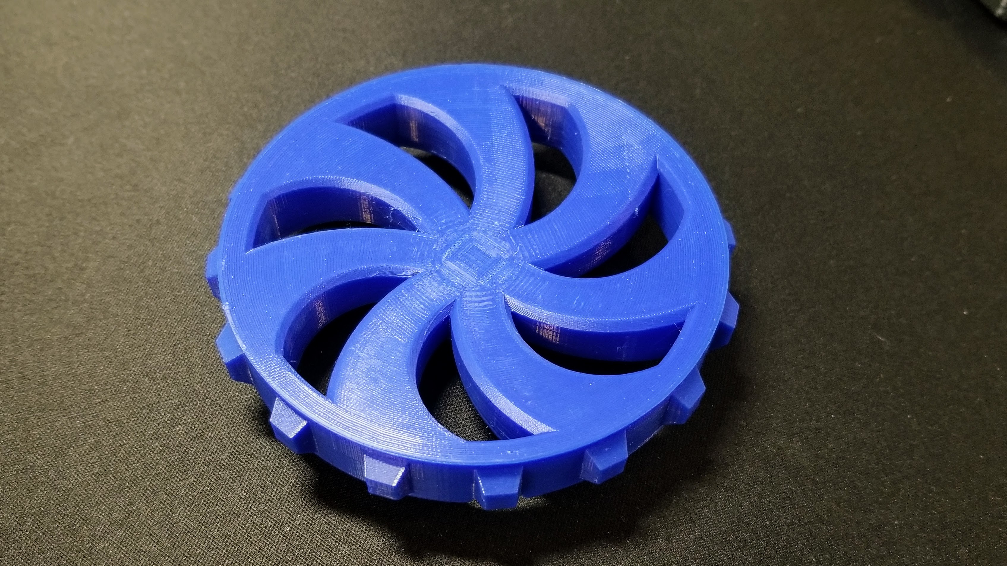
We have to mount the wheel to the motor shaft, but we don’t have any set screws, and if you screw into the 3D printed plastic that would strip out immediately. So we need to leave space to stick an M3 nut into the hub and screw an M3 screw into that. In the first test print, I only allowed a 0.1 mm tolerance on the hole for the shaft, and it fit on so tightly that we had to cut the print off. Oops.
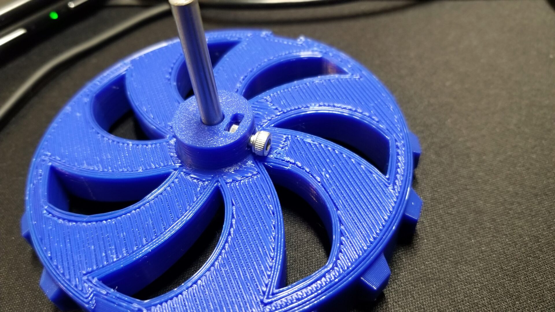
Consistent with our design goals for this robot, I want to get that nice curved/futuristic aesthetic. Most of the time for this was invested in getting the spokes to look just right. I also designed it with a curved front face, which means we need to print with that side up and a ton of support material on the underside/back (which no one will see when the robot is assembled). I was worried that the gently curved top surface would result in the ugly stair stepping effect that you get on 3D prints from the large layer height relative to the slope. However, the latest PrusaSlicer (2.2) comes with an automatic variable layer height, which reduces the layer height to as low as 0.07 mm for the most gently sloped areas. The result is much cleaner than I expected.
Tires
The wheels also need tires for grip, which we’re printing with Ninjaflex. Since Clark’s printer has a bowden extruder, it can’t print flexible materials. That means we’re printing it on my printer, which I’ve never tried printing Ninjaflex on before. So the first step here is to figure out the settings I need to print Ninjaflex. I started with this Ninjaflex printing profile for the Prusa MK3 that someone else made, and printed a 20 mm calibration cube. It’s the one on the left here:
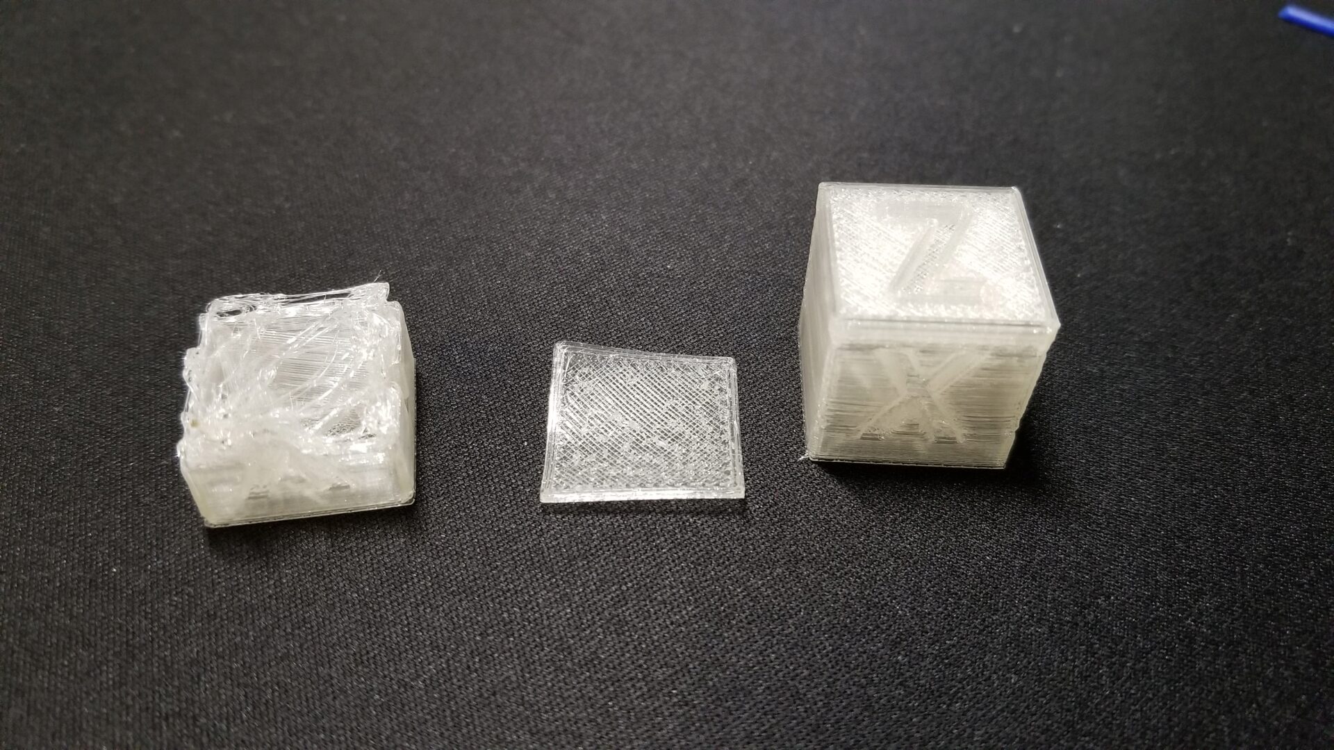
It started out so promising. So I tried again, this time turning off retraction, since that can cause flexible filaments to get backed up and wound around the extruder gears. It failed again. I tried turning down the print speed from 15 mm/s to 10 mm/s. Still failing. I got a number of prints like the middle one in that picture – frustratingly worse than my first attempt.
Eventually, I loosened the idler gear in the extruder and was able to get the cube on the left. Huzzah! Apparently having the gear too tight squishes the filament out of shape and makes it more likely to fail. I don’t understand the mechanics behind it, but it’s a common suggestion I saw online, and it worked. My cube definitely isn’t perfect. The perimeters didn’t adhere to each other and some of the layers separated. It was only printed at 15% infill, so that might have played a role. I think this clear filament is also particularly unforgiving when it comes to showing flaws, since every small detail/error reflects and refracts the light to make it as visible as possible. It’s good enough, though, especially since we’re printing the tire at 100% infill. So let’s invest 7 hours to print this tire!
I also make another fun discovery while trying to print Ninjaflex: if I unload it from the printer menu, it’s too fast and the filament gets wrapped around the extruder gears. I ended up unloading by slowing moving the extruder motor position from the settings menu.
6 hours and 53 minutes later, the tire actually printed successfully! We’re still seeing the perimeter separation, which seems to indicate that we’re getting consistent under-extrusion. Since it’s at least consistent, we could bump up the extrusion multiplier in the slicer to compensate. But it’s a functional tire.
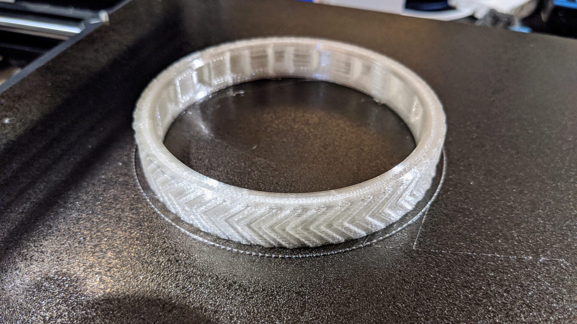
And I think it looks pretty dang good all put together:
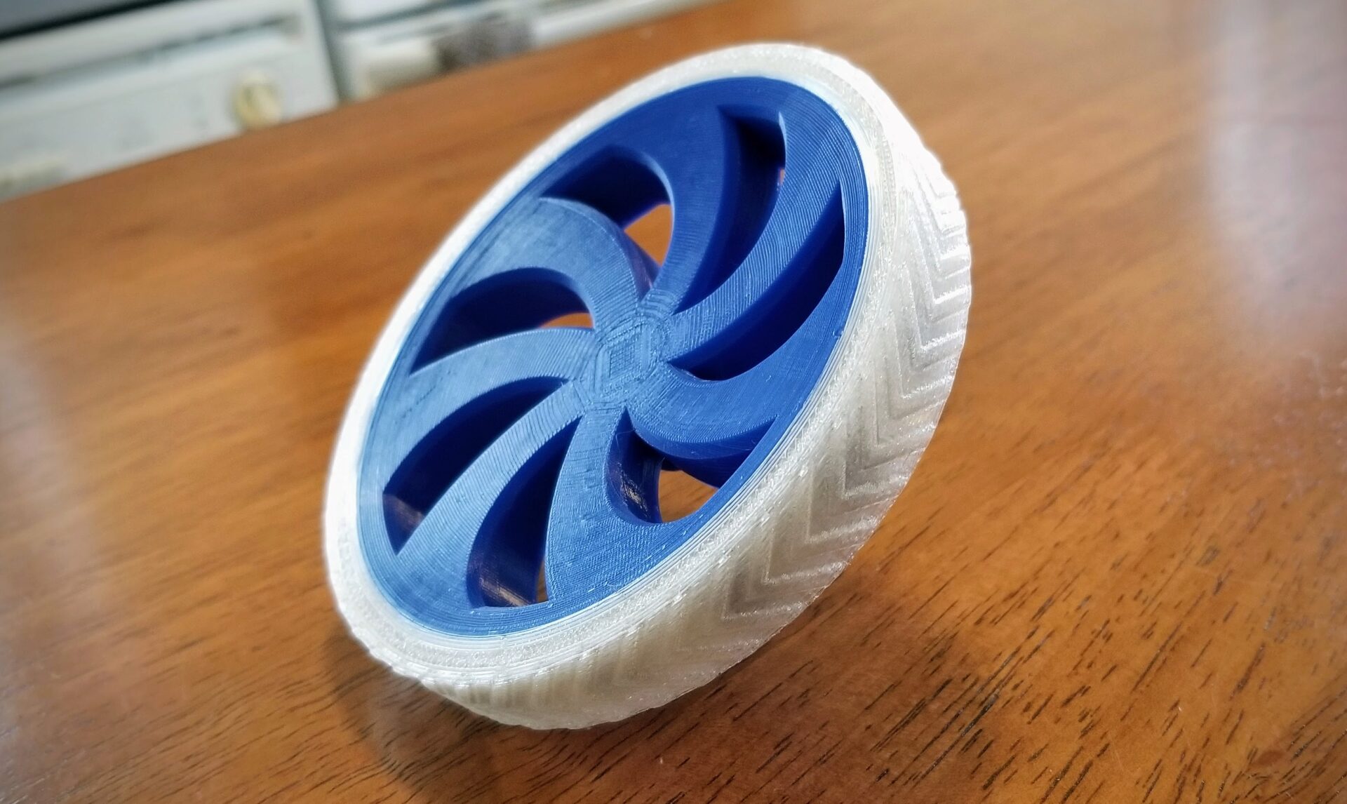
Let’s jump back a couple steps here to talk about the design of the tire. To make sure the tire stays seated on the rigid wheel and doesn’t slip, we have notches in the tire and corresponding nubs on the wheel to keep it in place. The size, angle, and number of these was pretty arbitrary, with one exception. Since the tire is printed flat, it has to be able to print the overhang angle for the sides of the notches, and Ninjaflex doesn’t like to print overhangs. I could have printed an overhang test, but I’m lazy, so I just made a guess that it could probably handle 40° from horizontal. It turned out I was right on that, but that’s a relatively shallow angle, which also allows a bit of slipping side-to-side on the wheel. (On the plus side, it’s pretty easy to get the tire on and off.)
There’s also another potential cause for the fit of the tire on the wheel hub. TPU like Ninjaflex tends to shrink when printed, relative to the specified dimensions. For rigid filaments, you typically need to give a tolerance of something like 0.2 mm (a gap) to get things to fit together. With TPU, you actually need to give a negative tolerance. For the tires, we added a tolerance of -0.5 mm on the round surface where it meets the wheels. But we didn’t add any tolerance to the notches, because we wanted to make sure the wheel stayed round and didn’t end up not fitting nicely over the nubs on the wheel. Once printed, though, this likely contributes to the small amount of slippage we see between the tire and wheel. The possible under-extrusion probably doesn’t help, either.
But do you know the phrase “good enough for government work”? Well, this is good enough for quarantine work. For the other tire, I can try adjusting the negative tolerance as well as the extrusion multiplier in the slicer. But I’m not going to mess with this one.
One last note on Ninjaflex. We were planning to also use it to 3D print timing belts for the arm. But even at 3 mm thick and 100% infill, the Ninjaflex tire still has some stretch to it, which is not what you want in a timing belt (or else you’ll get backlash). So this might not work as well as we’d hoped for timing belts.
Motorizing the Wheel
With both parts of the wheel complete, let’s put our NEMA 14 motor on it. The setup for actually running the motor is incredibly hacky: the stepper motor is connected to a RAMPS 1.4 board (intended to be put into a 3D printer), which is then connected to a Raspberry Pi, which is runnning Clark’s instance of OctoPrint (which is normally connected to his 3D printer). Then, from the OctoPrint web interface, we tell it to move the y-axis to run our motor.
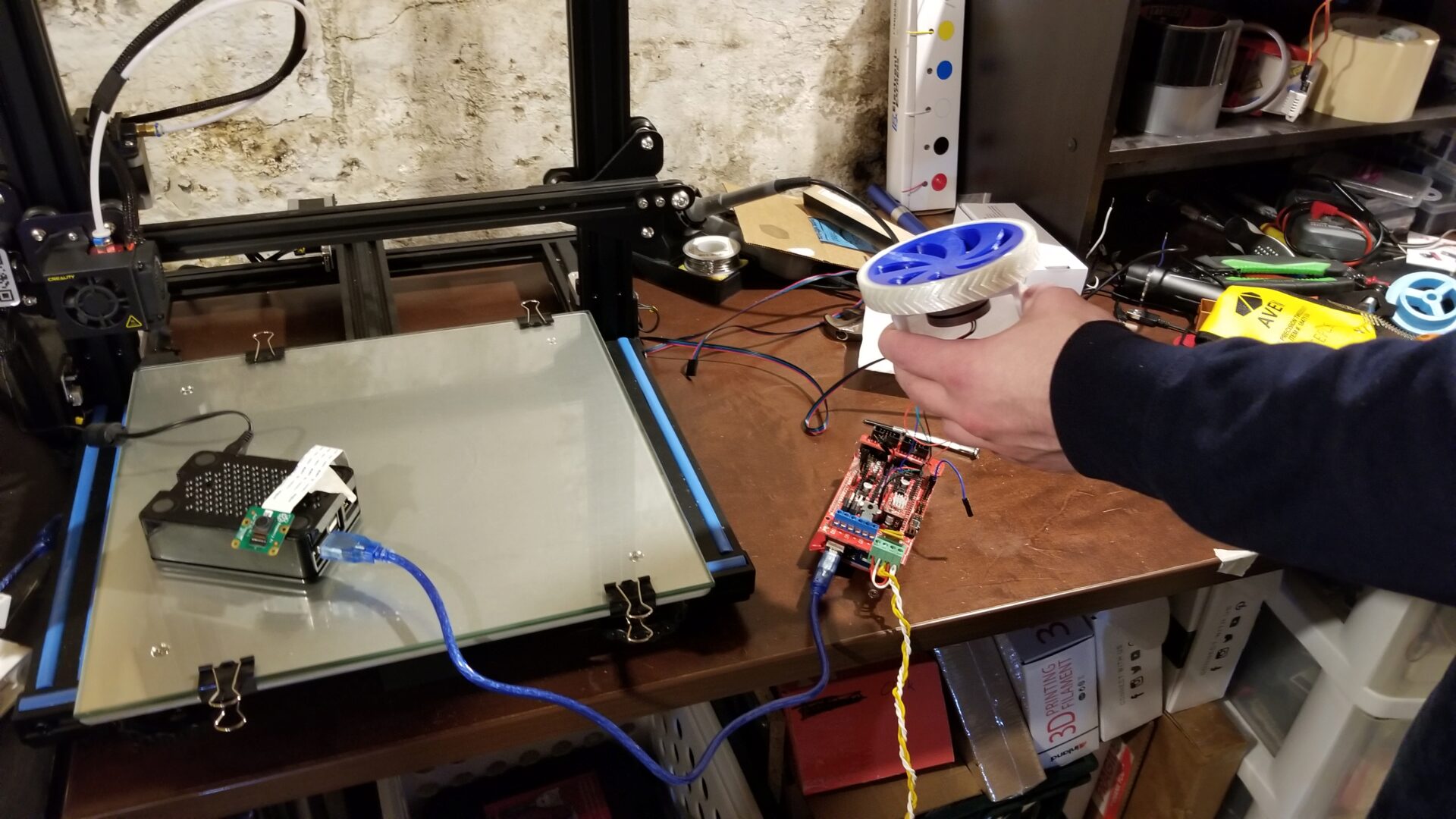
But hey, it runs!
…as long as there’s no load. As soon as you introduce any significant resistance (like you’d get from the weight of the robot), the motor can’t produce enough torque to keep going.
What about the beefier NEMA 17 motor? It’s slightly better, but it still can’t really produce enough torque that it would be able to move our robot around. It looks like our original plan of directly driving the wheels with the motors is a bust.
In true quarantine bot fashion, we now have to figure out an alternative with our scavenged scrap. We can gear the motors down, but that requires us to have a shaft and bearings for the wheel, plus gears. (One benefit of this, though, is that it will allow us to offset the motors from the line of arm motors and keep the robot body smaller.) We can 3D print some mediocre gears, so that should be manageable. And it turns out that Clark has some 3/16” dowels and bushings leftover from something else. 3/16” is close enough to the 5 mm motor shaft that I designed the wheels for, so it turns out that we can just stick it into the existing wheels and tighten down our makeshift set screw. (We don’t have a file, so we can’t give it a nice flat to grab onto.)
Printer issues
All of that glosses over many other incredibly frustrating and still-unsolved issues with my 3D printer that cropped up in the midst of all of this. But it’s too confounding to explain in detail here. I’ll add more when it makes me less sad.
Baby’s first gearbox
We’ve figured out that we need to gear down the motor to get enough torque, but now we need to figure out what the ratio needs to be. (There are reasons people don’t usually use stepper motors for driving wheels, and their low torque is one of the reasons.)
We need to make some estimates and assumptions for this calculation, such as the robot’s mass and how steep of a slope the robot can climb. (If quarantine bot is going to go do things for us, it probably needs to go up and down some ramps.) We want to compute the gear ratio \(\rho\), which needs to be at least the ratio of the goal torque at the wheel (\(\tau_g\)) and motor torque (\(\tau_m\)):
\[\rho \geq \frac{\tau_g}{\tau_m}\]Let’s start by computing the goal torque. For a rough approximation, we’ll start with the torque required for the robot to remain stationary (not roll down) the steepest slope we care about, an angle we’ll call \(\alpha\). The biggest force we have to worry about here is the force of gravity; with an acceleration of \(9.8 \frac{\text{m}}{\text{s}^2}\), this is a way larger factor than any forward acceleration (of perhaps \(0.5 \frac{\text{m}}{\text{s}^2}\)), as the slope gets steeper.
\[\tau_g = F_g \cdot r_w \cdot \sin \alpha = m_\text{robot} \cdot g \cdot r_w \cdot \sin\alpha\]The last piece we need for this calculation is the radius of the wheel, \(r_w\), which we already (rather arbitrary) picked as 50 mm (0.05 m).
The motor torque is a property of the motor, and it turns out the there’s some variation here, depending on the manufacturer and the individual motor. Based on one available on Adafruit, we picked a conservative estimate of \(\tau_m = 0.20 \text{ Nm}\).
To compute our gear ratio, we need estimates for the weight of the robot, and we need to pick the steepest angle the robot can handle. We estimated the robot mass mostly based on the weights of the heaviest things in the robot (such as 5 NEMA-17 motors, at 0.25 kg each), coming up with a rough estimate of 2.2 kg. For a goal slope, we picked 35°, which would let the robot climb a slope built over standard stairs, which have a 7:11 aspect ratio.
\[\rho = \frac{m_\text{robot} \cdot g \cdot r_w \cdot \sin\alpha}{\tau_m} \\ = \frac{(2.2\text{ kg})(9.8\frac{\text{m}}{\text{s}^2})(0.05\text{ m})\sin(35\deg)}{(0.20 \text{ Nm}) \\ = 3.1}\]A gear ratio of about 3:1 would let our robot not roll down a 35° slope, under ideal conditions. We haven’t accounted for any loss/friction in the system, uncertainty in our estimates (like that atrocious estimate of the robot’s mass), or letting the robot actually go up the slope. We’ve also assumed that the robot is only being driven by one motor, but we’ll actually have one for each of the two wheel. The easiest way to fix this is to add a safety factor. A 20% safety factor would mean a gear ratio of 3.72, and a 50% safety factor means a gear ratio of 4.65.
But as you increase the gear ratio, you also decrease the maximum speed (on flat ground) that the robot can achieve. With no gearing, it’s a simple calculation to go from the motor’s angular velocity (\(\omega_m\)) to the linear velocity. Pulled from an instructable, the motor can go at 800 RPM, or 83.8 rad/s.
\[v_\text{max} = r_w \cdot \omega_m \\ = (0.05\text{ m})(83.8\tfrac{\text{rad}}{\text{s}}) \\ = 4.19 \tfrac{\text{m}}{\text{s}}\]On flat ground, with no gearing (or a gear ratio of 1), the maximum velocity would be 4.19 m/s, if the robot can generate enough torque. That’s way faster than we’d want anyway, but that’s good. Because the maximum velocity is divided by the gear ratio \(\rho\), so this means we can increase the gear ratio (thus generating more torque) while still maintaining a reasonable maximum velocity.
| Safety factor | \(\rho\) | \(v_\text{max}~(\text{m}/\text{s})\) |
|---|---|---|
| 1.0 | 3.1 | 1.35 |
| 1.2 | 3.72 | 1.13 |
| 1.5 | 4.65 | 0.90 |
| 2.0 | 6.2 | 0.68 |
So what do we pick? The options we have for gear ratios are determined by the gears we have available. In our case, we’re going to be 3D printing the gears, so they’ll need big teeth to not strip/break. And because we don’t want to reinvent the wheel (or in this case, the gear), we’re going to 3D print gears that are available on McMaster, since they provide the CAD files.
Narrowing down our gear options on McMaster, we pick plastic gears with a 14.5° pressure angle. This mostly means we need to pick the pitch, which is how many teeth per unit of distance; the smaller the pitch, the bigger the teeth. It also means a larger gear diameter for the same number of teeth, and more backlash. Clark went through and looked at the pitch options and settled on a pitch of 32. This has a lot of options for ratios (as seen here), while providing a good compromise on size: big enough to 3D print, but small enough that the large gears will still fit in the robot. (If you have a gear with too large of a diameter, you’d reduce the robot’s ground clearance.)
If we use the smallest (12-tooth) gear for the motor, that leaves us with gear ratio options of about 4 or 5. To play it safe (and design our motor mount the worst case), we started with the higher gear ratio and picked the 62-tooth gear.
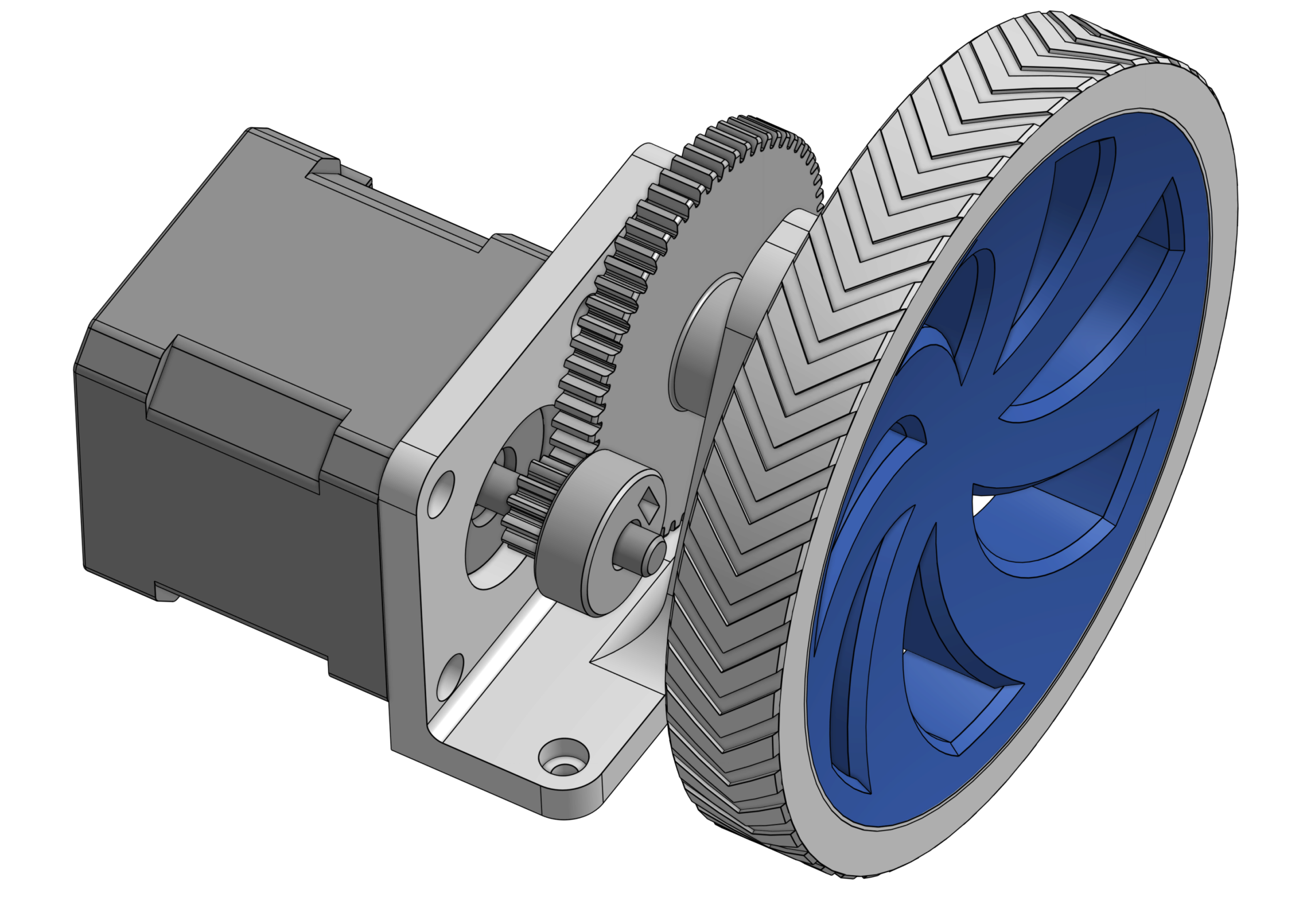
Once you’ve made those decisions, designing the mount to put all of this together was a lot easier than I expected. With the gears picked, you know the pitch diameter of each gear, which tells you exactly how far apart you need to place the gears. From there, everything else is known: the mounting holes for the motor, the size of the bushings we’re using as bearings (salvaged from an old project of Clark’s), and the diameters of the shafts we’re attaching our gears to. We did have to make some modifications to the gear CAD files from McMaster, to match the shaft hole sizes and add in our custom nut and set screw configuration (like I did for the wheels).
The trickiest bit of this design was dealing with the limited length of the 3/16” dowel we’re using as the wheel shaft. It’s only 1.5” long, and we need to use that to fit into the wheel, through the outside of the robot body, through both bushings on either end, and fit the gear in between. We had to squeeze the gear into a 13 mm slot. This gear also has to serve a secondary function: it’s what’s holding the wheel in place. The bushings on either side let the wheel shaft turn smoothly, but the gear in between is what keeps it from sliding out of the body. It’s not ideal, since the sides of the gear are rubbing against the surface of the bearings, but in typical form, it’s good enough for quarantine work.
And with that, we have my first ever gearbox:
We two of printed all the parts in PETG, and discovered that this required some assembly tricks: you have to attach the motor first, because you can’t get to the screw holes once the big gear is in place. But that’s a small one-time limitation, nothing major. The real test comes when we run it. To make the simplest robot possible, we screwed the drivetrain and caster wheel to a piece of MDF from sacrificed IKEA furniture scrap.
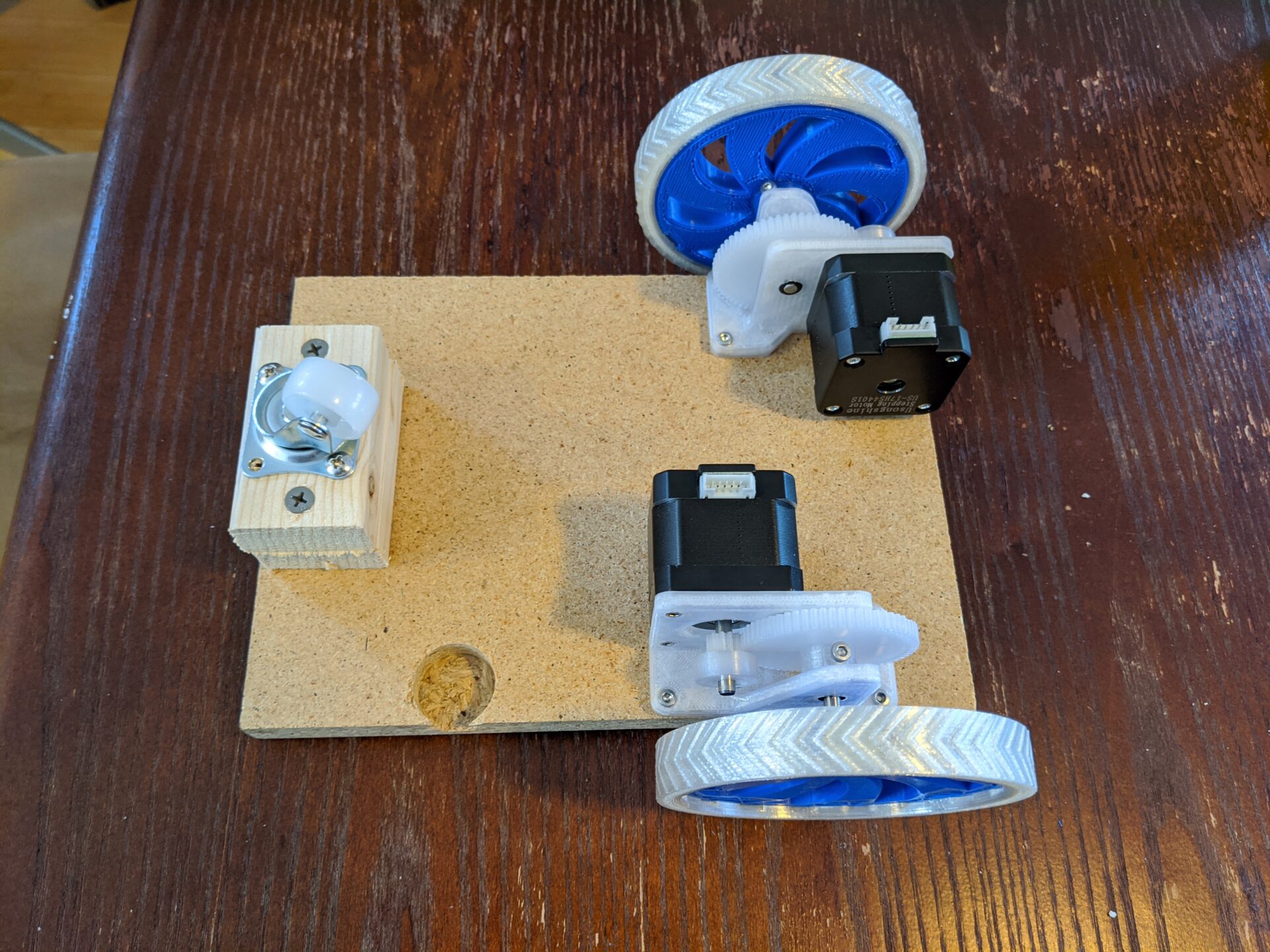
But once you throw some googly eyes on it, it looks like a real robot!
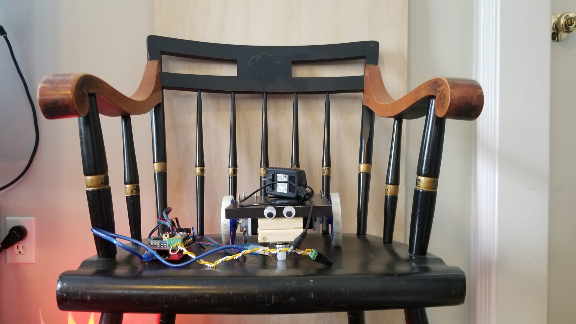
But does it work? We connected the motors to the driver board running Marlin and Clark sent it g-code from his laptop. (We’re leaving out the Raspberry Pi running OctoPrint this time, but we’re still pretending it’s a 3D printer. Eventually we might write real firmware for this.) It’s now doubly-tethered, to the computer and a 12V power supply. We “built” a ramp with a sheet of plywood on the couch to test whether this could actually climb a ramp like our assumption-filled calculations say it should.
It works! It can go straight. It can turn. It can climb. This is actually starting to behave like a real robot.
Next up, I want to design the body and figure out how all of this is going to fit together. For now, though, I’m waiting on Clark to figure out how he plans to organize the motors for the arm. In the meantime, I should work on the high-level software and control side that will run on the Raspberry Pi. Actually, the weekend’s over and now I should do my actual research work. But that doesn’t seem like as much fun as hacking together a Pi, RealSense camera, and USB AI accelerator for object recognition.
Object Detection
While we’re busy printing parts for the arm, and while Clark is hacking at the Marlin firmware to make the motors work… I should probably get started on the software that will run this robot.
Since I’ve got this new Coral USB Accelerator and Intel RealSense camera sitting on my desk, it seems like a good place to start is sticking them together to detect thing in the environment. We’ll give our non-existent robot some eyes!
Before I get into this, let me preface this by saying that this ended up being a huge rabbit hole (which seems to happen a lot). Both Intel and Google have polished advertising for these products, but under the hood, there’s a lot of inconsistency, changing APIs, and limited support for different platforms.
In the end, the goal is to run this on a Raspberry Pi 4, but to make debugging easier, I decided to start by setting up and running things on my desktop computer (running Ubuntu 19.10). Naively, I thought I could just start by running this Pi + RealSense + Edge TPU code for object detection that I found on GitHub.
Of course, it didn’t work. I was beset with errors from the start, in part because that code came with zero instructions. As I went, I use pip to install every Python package the script complained it didn’t have, until I ran into the complaint that it couldn’t find the edgetpu module. That’s apparently something Google didn’t feel the need to put into PyPi to make things easy to use. Instead they only provide it as a system package. So now, I’m going to have most of my packages installed in virtual environment, and this one package and its dependencies as a system package. And if I’m using the virtual environment for my python path, I don’t have access to that system package. I found this GitHub issue that solved my problem with an incredibly hacky workaround: adding the system distribution packages to my PYTHONPATH when I’m in the virtual environment. I don’t like that solution, but at least for the moment, it lets me move on… to the next error:
AttributeError: 'Delegate' object has no attribute '_library'
No idea what that means. The classic game of Googling the error eventually led me to this GitHub issue, where it seems that the issue is related to accessing the device over USB. I checked that it showed up with lsusb. I tried adding my user to the plugdev group. I added this mysterious rule. I rebooted my computer multiple times. No dice.
Eventually, I realized that there are two different APIs for using the Edge TPU. One is edgetpu, and the other is tflite, which is a lower-level interface. Desperate to make something work, I actually went back to the beginning and read the beginning of the documentation: Get started with the USB Accelerator.
Look, comprehensive instructions! A way to install the the TensorFlow Lite library with pip. (There’s a caveat on that, since they still aren’t using PyPi, so you have to tell it the URL to get the package from, and it’s different depending on what OS you’re using.)
- Install the Edge TPU runtime on the system:
echo "deb https://packages.cloud.google.com/apt coral-edgetpu-stable main" | sudo tee /etc/apt/sources.list.d/coral-edgetpu.list
curl https://packages.cloud.google.com/apt/doc/apt-key.gpg | sudo apt-key add -
sudo apt-get update
sudo apt-get install libedgetpu1-std
(At this point I accidentally uninstalled that package and spent half an hour tearing my hair out trying to figure out why later stuff didn’t work.)
- Install the Python package: (Instructions here). Here you need a different file depending on your Python version and your computer architecture (ARM, x86, etc.). I’m on x86 using Python 3.7 (for now), so I used the following:
pip3 install https://dl.google.com/coral/python/tflite_runtime-2.1.0.post1-cp37-cp37m-linux_x86_64.whlIf you try to create a requirements file from this using
pip freeze, though, it won’t work. I’m still working on a fix to automate that, but for now you’ll have to run that command manually. - Download and run the example image classification code:
mkdir coral && cd coral
git clone https://github.com/google-coral/tflite.git
cd tflite/python/examples/classification
bash install_requirements.sh

python3 classify_image.py \
--model models/mobilenet_v2_1.0_224_inat_bird_quant_edgetpu.tflite \
--labels models/inat_bird_labels.txt \
--input images/parrot.jpg
Look, we found a bird!
This ended up being way more straightforward than the edgetpu API. Which is kind of ironic, because that API is supposed to be higher level and easier to use. But it’s amazing how much better this works when I actually read the instructions.
This example repo also had an object detection example, which was equally easy to run (and helpfully told me that the picture of Grace Hopper contained a person and a tie). That’s the more interesting thing to me, since that’s what we’re planning to do with our video.
So far, these examples are running on single, saved images. We want to use a video stream. Guess what? They have an example for that on GitHub. It turns out to be almost exactly the same thing as the previous object detection example, but with the functions written ever so slightly differently. Basically, it was written by a different person with slightly different opinions about the code structure, but who used the same function names. But it turned out I couldn’t use that code, because it’s set up to get camera data from a regular webcam, not a RealSense camera.
But hey, I’ve got an example of how to use the RealSense camera from that other realsense object detection code. So I basically glued that camera code together with the object detection code from Google’s camera example repository. I cleaned it up a bit, and we can do object detection from a live video stream at about 35 frames per second.
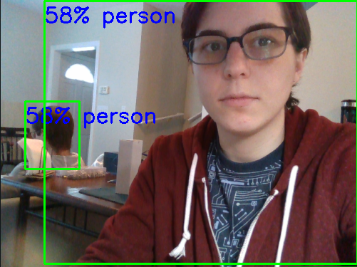
Apparently there’s a 58% chance that I’m human.
I cleaned up the code a bit and pushed it to GitHub. You can check out the code here. (This links to that particular commit, not the most recent code, since I’m sure it will change dramatically.)
On the Raspberry Pi
I booted up the Raspberry Pi, prepared to just download and run what I’d spent most of my Saturday on.
Of course it didn’t work like that. I cloned my repository and ran my setup script. I ran my installation script and hit my first snag: it couldn’t install opencv-python. That turned out to be an easy fix; my requirements.txt wanted version 4.2, but it turns out that the latest version available for ARM is version 4.1. I manually ran pip install opencv-python, then updated my requirements file with pip freeze > requirements.txt.
Then pip failed to install pyrealsense2. And that is not an easy fix. According to this GitHub issue, “Unfortunately, we still not ready to publish pip packages for ARM architecture.” In 2018. It’s 2020. Based on the further comments, they still don’t support ARM. They tell you to [build it from source] (https://github.com/IntelRealSense/librealsense/tree/master/wrappers/python#building-from-source). Based on the further comments, this looks non-trivial. And yet another GitHub issue makes that task look even more onerous. Oh look, another GitHub issue about the struggles of getting the RealSense library to work on a Pi 4. It seems like there are two problems: first, you need to get the underlying library to work on a Pi 4, and then you need to compile the Python wrapper. This seems like something I don’t want to start at 7:00 PM if I want to go to bed at a reasonable hour.