Plotter In Progress
Posted: 2020 July 26
Last updated: 2020 July 27
- The starting point
- Our first version
- Making it plot
- Better plotting with bearings
- To Do
- Bill of materials
This was supposed to be a super straightforward weekend project: just build a Cartesian plotter that someone else had already designed, out of scrap parts we already had around the basement.
You can guess that it didn’t end up being quite so easy.
Instead of a weekend, it took about a week and a half, some CAD redesigns, and a few Amazon orders. But in the end, Clark and I actually successfully built a pen plotter!
The starting point
A plotter is like a CNC mill, but with a pen instead of an endmill. I ran across the idea of building one when I was figuring out how to procedurally generate terrain for a research project. In the process, I ended up going down a rabbit hole of procedurally generated art. It turns out that there is really cool art out there that people create by programming, and then transfer from digital to physical with plotters. There are some cool examples on Reddit’s /r/PlotterArt and a website I found called Generative Hut (to name just a few).
It turns out that the favorite plotter among these artists is the AxiDraw. And it seems to be the only commercially-produced consumer-level plotter out there. Welp.
But someone must have figured out how to make their own, right? It’s basically a 3D printer without the z-axis. You need two axes (powered by two stepper motors), and then (like the AxiDraw) a servo to move the pen up and down. Of course they have.
The most popular plotter design on Thingiverse is the DrawBot. It uses a CoreXY design and a bunch of linear rails. This has the benefit that there’s no motor on the Y-carriage, which make it a lot lighter. We didn’t end up going with this choice for a simple, lazy reason: we didn’t have a long enough timing belt. We wanted to used pretty much just what we had on hand (who wants to wait two whole days for Amazon order to arrive?), which was mostly parts from Clark’s old Anet A8 printer. (RIP. Long live the CR-10S.)
I also found this DIY Pen Plotter from Andrew Sleigh. He actually has three different versions of his plotter as he progressed through his design, with V3 using v-slot rails for the x-axis. But we didn’t have any of those (we’re not scavenging the CR-10S for parts), so we decided to build V2, which uses linear rails for both the x- and y-axes. Conveniently, he provided his 3D files on Thingiverse, including his Fusion 360 file. But he didn’t really give any instructions, or any details about what other parts you’d need besides the 3D prints. From his pictures and short video, though, we were able to piece together what was going on. (Hopefully, we’ll have a complete bill of materials at the end of this.)
Our first version
Before we dove in, though, we realized right off the bat that we’d need to make some modifications.
- This design used 10 mm linear rails for the x-axis. We only had 10 mm rails, so we needed to resize the holes for both the rods (on the x-axis end pieces) and the bearings (in the gantry) for
- There was no way to tension the belts. Clark has drilled into my head that you always need a way to tension your belts, so we’d have to add a tensioning mechanism for both axes.
- To assemble the two gantry pieces, you need some crazy long M3 screws (at least 40 mm, I think), which we didn’t have. So we had to recess the nuts in the bottom gantry piece to get away with using 30 mm M3 screws (which are the longest you get in the cheap sets of screws on Amazon).
Once we started printing things, we ran across other issues, which I’ll get into more below. One common one, though, was tolerances: the through-holes for the M3 screws (which was most of the build) were all too tight (they were basically self-threading), and the holes for the corresponding M3 nuts were all slightly too large.
We were glad the original creator included his Fusion file, since it would make our modifications easier. When we opened it, though, we were left scratching our heads a bit. It’s unclear whether something was broken with the file, or it just didn’t contain everything, but we only sort of had the source information. There was an assembly, but it didn’t include the history of the source parts. But this assembly seemed to contain some of the creation process, mostly fillets. So all the changes we made were a little hacky, but at least we didn’t have to deal with directly modifying the STLs or reverse-engineering the parts from STLs. (Both of which I’ve had to do before. Not fun.) Also, since Fusion doesn’t run on Linux, it was actually Clark doing all of the modifications.
After adding in tensioners and modifying the design for 8 mm rails, we parallelized our printing between our two 3D printers, which meant printing in white PETG, because that’s the only color of PETG we have 2 rolls of. We went with PETG over PLA for its vastly superior structural properties. We also weren’t going to print with ABS (or similar) because we didn’t want to create toxic fumes, and also because we don’t have any.
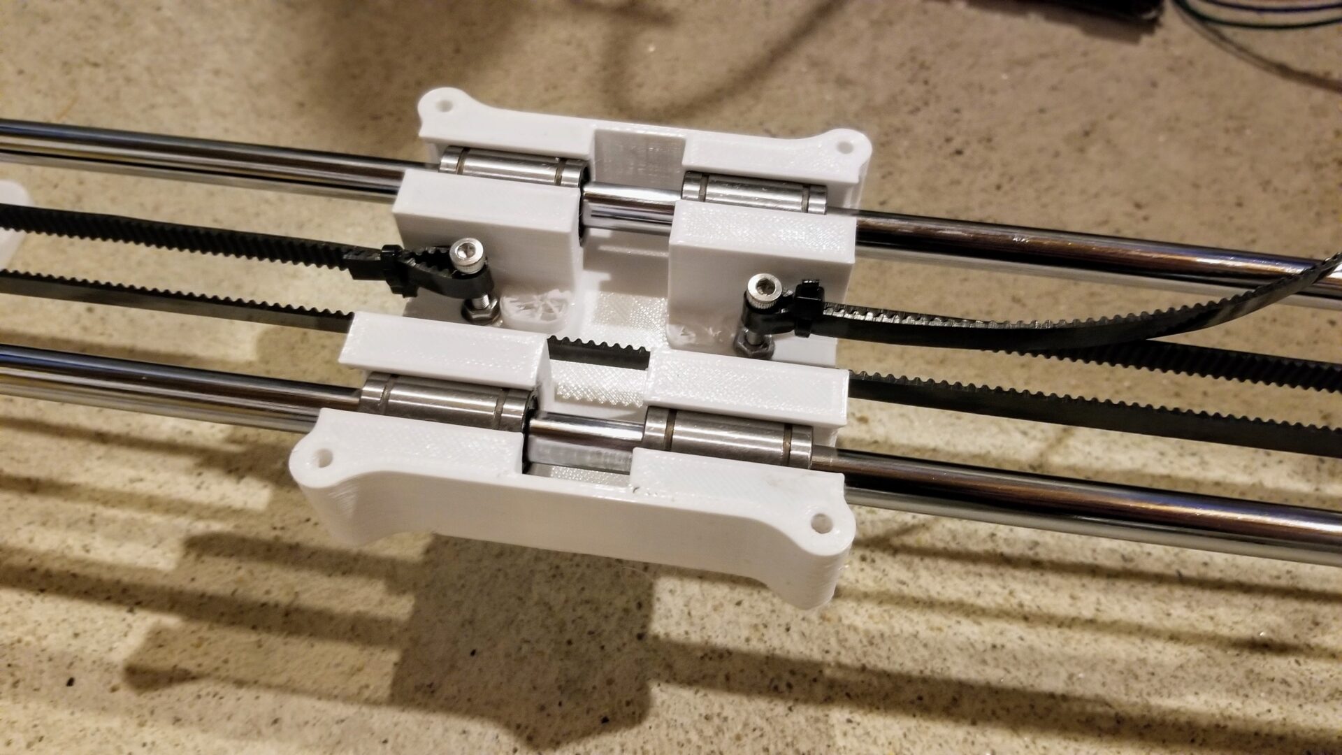
Check out that y-axis! (Yes, it’s a mess. No, we don’t have enough workspace. But hopefully we will after we move!) You can see our new y-axis tensioner in place, with the timing belt zip tied in place. (We found that using 2 zip ties on the ends of the belt made it feel much more secure.) In front of this is the tensioner for the x-axis, with idler bearings scavenged from the Anet A8.
The original design we used didn’t give details about firmware or how to actually control the plotter, but both his V3 and the DrawBot (mentioned above) use GRBL, which runs on an Arduino with a CNC shield. Specifically, they use the GRBL Servo fork, which includes support for controlling the servo motor that lifts the pen. We don’t have an Arduino CNC shield, but we do have an SKR 1.4 board (sorry, Quarantine Bot), and Clark knows how to set up Marlin. As a bonus, Marlin and the motor drivers support sensorless homing, so we can even make the plotter home itself before every plot!
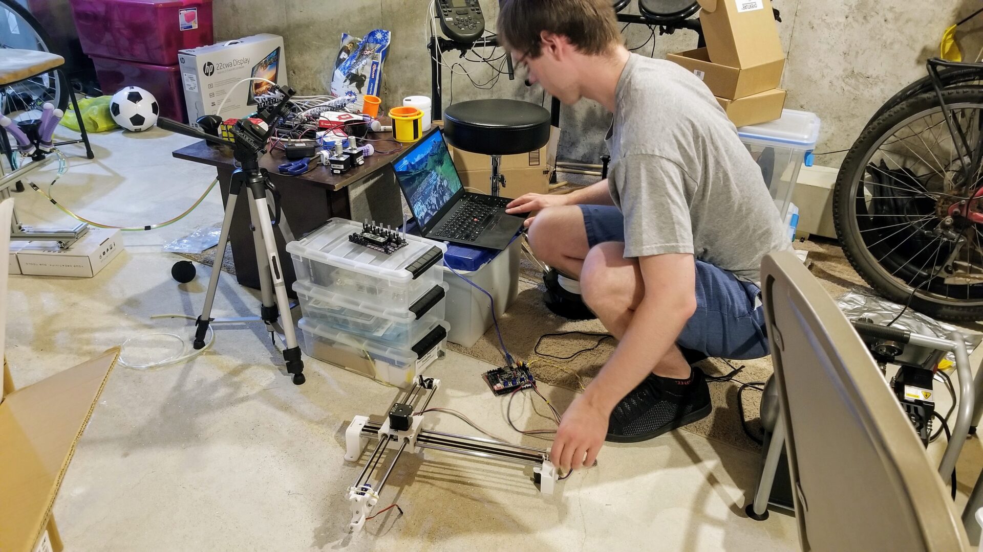
Our testing setup is equally as sketchy as our assembly bench. And it’s also serving as a home robotics lab while we’re all doing work and research from home. The first test was to see if we could get Marlin to compile, move the axes, and home itself. It compiled, after telling it that (since this isn’t actually a 3D printer) we don’t have an extruder or z-axis or any heaters. At this point, we weren’t worrying about getting the servo yet. Using Pronterface to directly send G-code directly to the printer (er, I mean, plotter), we could get both axes to move. Success!
… Until we tried to do the homing and broke the plotter.
To hold the ends of the belts in place on the x-axis, this design used some ridged plastic bits that you stuck the belt into, hoping this would be enough to keep the belt from slipping. It wasn’t, so we added zip ties to the ends of the timing belt (like for the y-axis). But when we tried to home the plotter, it just broke the plastic standoffs. Oops.
We later discovered that this was partly caused by having the homing sensitivity set too low in the firmware, but we took this as a chance to redesign the way the belt ends were held in place, instead using M3 screws and zipties. As a short term solution before we re-printed parts, though, we just drilled holes through the broken part and added in screws. Also in the homing process, we broke one of the ends of the x-axis, because the piece holding the tensioner was too thin. So that’s another part to modify and re-print!
With those newly-fixed parts re-printed, we have something that looks like a functional plotter.
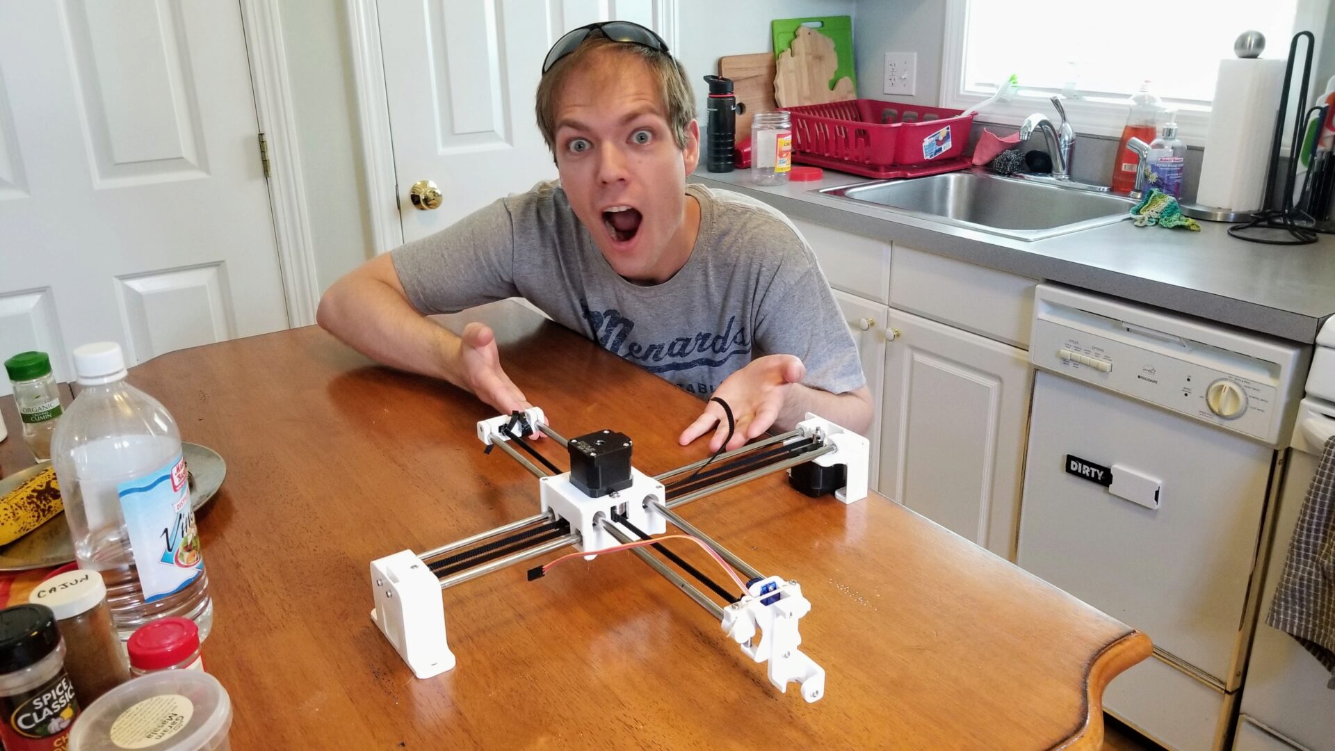
Clearly very exciting. (Ignore the fact that none of the motors are actually connected to anything here.)
Making it plot
You know that saying that the last 10% of the something takes 90% of the work? That definitely held true here. The x- and y-axes are fairly straightforward, since they’re exactly like a 3D printer, and Marlin is nicely set up for this. But the servo turned out to be a bit trickier.
We saw two potential ways to control the pen servo. You could just use it as a servo directly. Configured in Marlin, you’d control it with the M280 command, setting the angle you wanted the servo to go to. For example, to go to 90°, you send M280 S0 P90. Or, you could pretend that the servo is a laser! This is the objectively cooler-sounding option. This lets you use the built-in M3 and M5 commands to turn the laser off or set its power, which, like a servo, is just a PWM signal. Somehow, this turned out to be a harder option to set up, and for awhile we couldn’t get it to work because we’d enabled both of these options, which just resulted in the servo doing nothing. So we ended up going with the servo M280 option.
With the firmware configured, now we actually need some G-code to plot. With a bit of googling, it turns out that a popular option is generating G-code from SVGs in Inkscape using an extension from J Tech Photonics. This extension is designed for laser cutters, but thankfully, it lets you configuring the commands for tur ning the “laser” on and off, so we could just tell it to use M280 instead of M3. Sweet! (Side note: I’ve started digging into the code of this extension to modify, and the code is kind of a mess. Among other issues, I think it’s Python code written by a C++ programmer.)
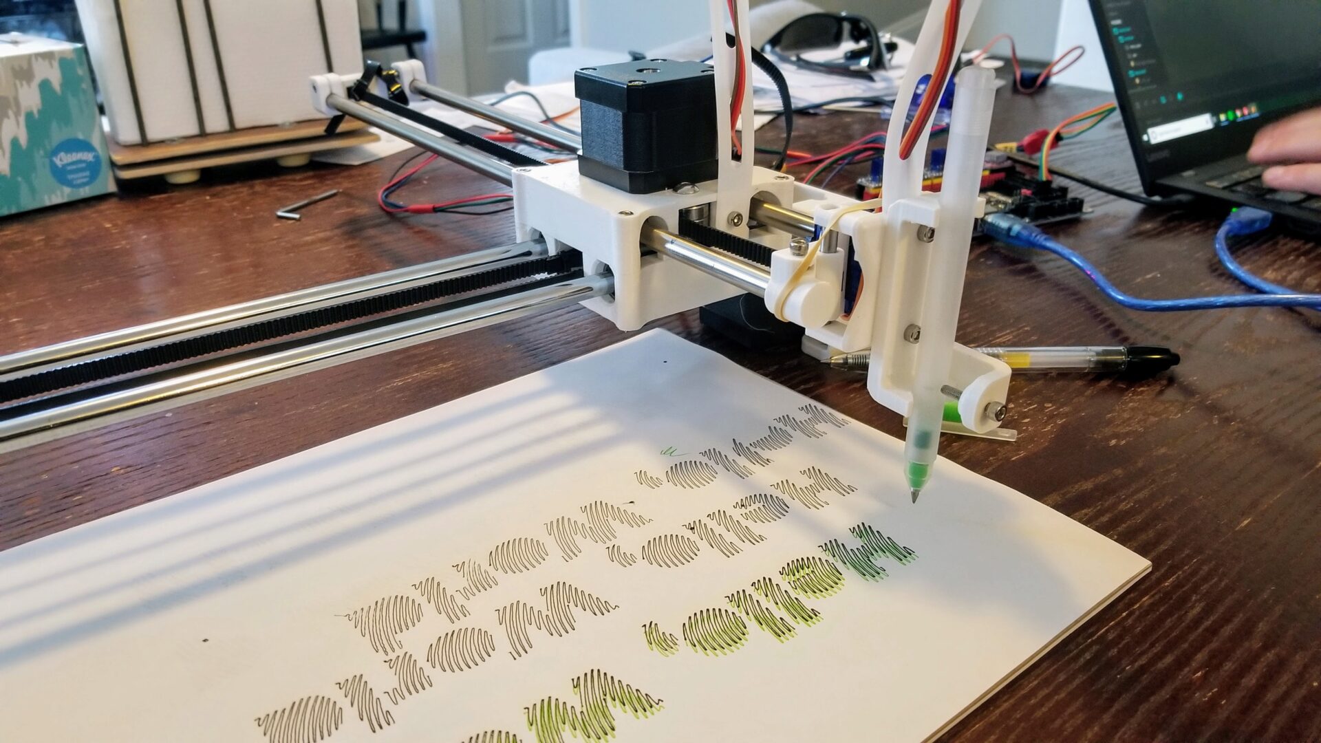
The first thing to make the plotter say is, of course, “Hello World”. But let’s make it cool and squiggly, for fun. (That actually turned out to be a pretty good torture test.)
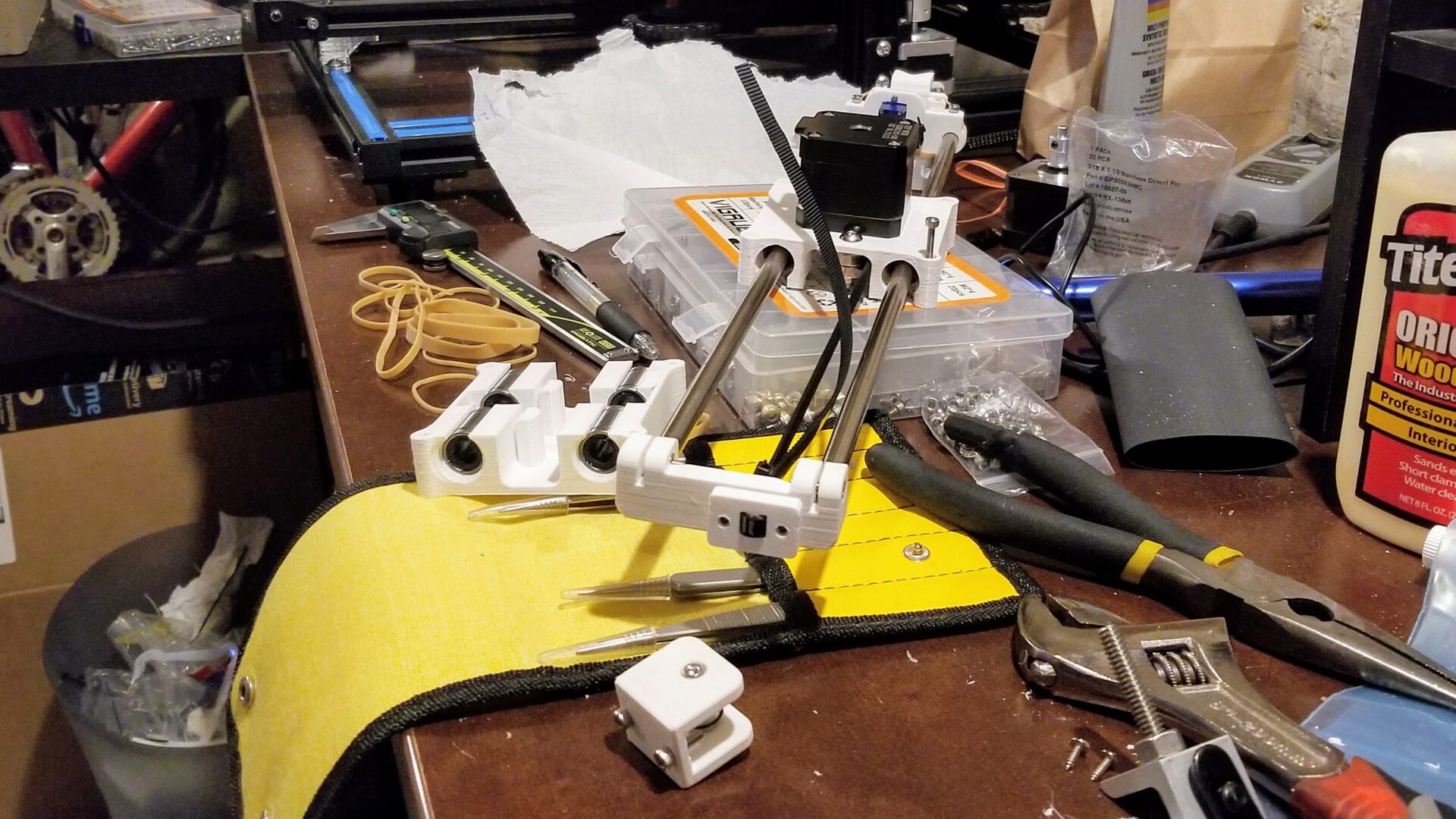
It actually kind of works! You can already spot a couple of issues here. The most obvious is that we’re not drawing consistently on the paper. There are a couple problems contributing to this. First is the sag of the x-axis linear rails; the closer we are to the middle of the x-axis, the lower the y-axis gantry sags. It’s not a lot, but it’s enough to cause an issue with something as precise as a pen in contact with paper. You also get some sagging when the y-axis is all the way extended, but at this point the contraption is unsteady since it’s not mounted on anything. So we’ll ignore that problem at the moment and worry about it later.
The second issue (which turned to be a bigger challenge) was the actuation of the pen. In the original design, the servo horn bumps up against a plastic piece to push the pen up, and then relies on gravity for the pen to go down. The gravity approach had two issues: first, our bearing surface of 3D printed plastic on metal down pins was far from a high-precision bearing surface, even with liberal application of Super Lube, so the pen often wouldn’t drop down on its own. Second, gravity alone doesn’t generate a lot of downward force on the pen tip, so we didn’t get consistent enough force to draw nice lines. You can see our first-pass solution above: just stick a rubber band on it to pull the pen carriage down when the servo isn’t engaged. As I’ll get into below, we ended up doing a lot of work to improve this.
You might also notice that the lines it’s drawing are kind of shaky. We’d made some pretty arbitrary guesses about the speed and acceleration of the axes, and they turned out to be too high. By turning down the acceleration in the firmware, we were able to get much smoother drawing, at the cost of slower plots.
Better plotting with bearings
The plotter technically works. It probably works as well as the demo video on Andrew Sleigh’s website, where you might notice that it never shows the pen “retracting.” Sneaky, since we discovered this was the trickiest part of the whole build.
After plotting “Hello, World” over and over, we ran into a problem: we killed the servo. We’d overheated it. In fact, it had gotten so warm that it started to melt/deform the plastic holding it in place with M2 screws. Adding some M2 washers fixed that second issue, but we had a bigger problem. When the servo pulled the pen up, it was constantly engaged and had to produce enough torque to counteract the rubberband(s). If we used a weaker rubber band to limit this, there wasn’t enough force to push the pen down. It turns out that Marlin has an option to turn off a motor once it gets to its target position. Awesome! Except that once the motor was turned off, there wasn’t enough force to keep the pen up. It’s a catch 22.
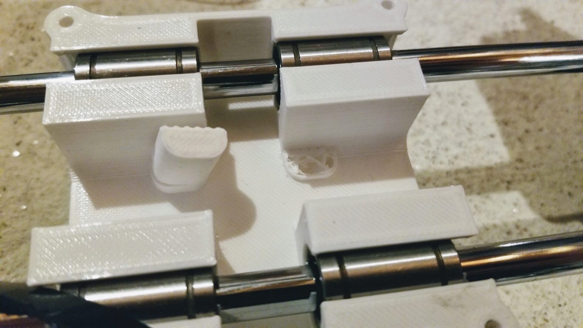
What if we could reduce the necessary rubber band strength by letting the servo help push the pen back down? We added a second lever for the servo horn to hit. Now it would hit one bumpout to push the pen up, and when you told the pen to go down, the servo would hit the other one and help overcome the static friction resulting from our crappy bearing surface. It worked… sort of. I mean, it was better, but it still wasn’t super reliable or consistent. We really couldn’t get around the limitations of our 3D printed bearing. Plus, the whole pen carriage was kind of wobbly; because we couldn’t put tight tolerances on the bearing tube, there was a lot of hysteresis between moving the axes and moving the pen.
So we caved and ordered some cheap bearings. Previously, we were using some leftover Imperial-sized dowel pins that luckily happened to be almost exactly the right size for the initial design. But to find compatible bearing parts, we ended up ordering 50mm x 4mm steel dowel pins and corresponding linear ball bearings. While we were at it, we got some springs, hoping to eliminate the unsightly rubber band hack. We went with what you could get cheap on Amazon with Prime shipping, so we’re not talking high precision here; the dowel pins were advertised as being good for assembling bunk beds. They did actually turn out to have pretty tight diameter tolerances, but when you rolled them on a flat surface, you could see that they weren’t all perfectly straight. So we picked 2 of the straightest-looking ones out of our 10-pack.
We originally planned to use two bearings on each side of the pen carriage, which would hopefully make it less wobbly, but the curvature of the dowel pins nixed that idea. If you put two bearings next to each other and moved the rod, they tended to bind. Clark also partly blames the cheap bearings for this. Either way, we settled on putting just one bearing on each side.
From our assortment of random springs, we also put a spring around the dowel rod on one side of the pen carriage. The idea was that this would help keep the pen pushed against the paper, like the rubber band. Originally, were were going to put a spring on both sides, but it turned out the little servo couldn’t handle pushing the pen up against that much spring force.
To be continued.
To Do
Right now, the workflow for using this is pretty hacky:
- Create your SVG file
- Use the J Tech Photonics extension (with the right parameters set!) to generate the G-code
- Connect your computer to the plotter via USB cable to the SKR board
- In Pronterface, run the homing script
- Also in Pronterface, run the G-code file. You have to stay connected to the plotter until it’s finished.
I’m now working with a fork of the J Tech extension that I’ve hacked at, which I should be able to use to directly include homing into the script. AxiDraw has its own Inkscape extension for plotting, so I might also see if I can steal (er, borrow) some ideas from that.
The physical setup is also a bit hacky; the control board is stuck to the board is double-sided tape.,
To clean up the hardware side, we want to add a Raspberry Pi running OctoPrint, thus fully integrating it into our printer menagerie. And, of course, print a nice enclosure to hold both the Pi and control board. From what we’ve seen so far, we’ll also probably want to include a fan in there to keep the motor drivers cool.
Bill of materials
This isn’t complete yet. I’ve included Amazon links for parts we actually bought for this.
| Item | Quantity |
|---|---|
| Mechanical | |
| NEMA17 stepper motors | 2 |
| 8 mm linear rods (paired lengths, for each axis) | 4 |
| 8 mm (inner diameter) linear bearings | 8 |
| G2 timing belts (length based on rods) | 2 |
| Idler bearings for y-axis | 2 |
| X-axis idler bearing | 1 |
| SG90 9g servo motor | 1 |
| 4 mm x 50 mm steel dowel pins | 2 |
| 4 mm linear ball bearings (LM4UU) | 2 |
| Spring for dowel pins | 1 |
| Electronics | |
| SKR 1.4 control board | 1 |
| 12 V power brick | 1 |
| Motor drivers | 2 |
| Hardware | |
| Zip ties (for timing belts) | |
| M3 screws, washers, and nuts (various) | |
| M2 screws, nuts, and washers (for servo) | 2 |
| M5 (or imperial) screws and nuts (for y axis bearings) | 2 |
| M5 or M6 screws and nuts (for mounting) | 4 |
| PETG printer filament | |
| Rubber band(s) |
Non-consumable equipment:
- 3D printer